Integrated electric wheel system with de-energized electromagnetic parking brake

A braking device and electromagnetic brake technology, which is applied in the direction of brake actuators, gear transmission mechanisms, mechanical equipment, etc., can solve the problems that the electromagnetic brake is connected with the outer rotor motor, etc., so as to avoid parking brake failure, avoid motor heat damage, eliminate the effect of mechanical connection

Active Publication Date: 2016-08-31
JILIN UNIV
View PDF11 Cites 0 Cited by
  • Summary
  • Abstract
  • Description
  • Claims
  • Application Information

AI Technical Summary

Problems solved by technology

The action time of the electromagnetic brake is only tens of milliseconds, the engagement is reliable, and it can be directly connected to the traditional inner rotor motor, but the scheme of connecting the electromagnetic brake to the outer rotor motor has not yet been seen.

Method used


Image

  • Integrated electric wheel system with de-energized electromagnetic parking brake
  • Integrated electric wheel system with de-energized electromagnetic parking brake
  • Integrated electric wheel system with de-energized electromagnetic parking brake

Examples


Embodiment Construction

[0026] The present invention will be described in detail below in conjunction with the accompanying drawings.

[0027] The overall structure of the integrated electric wheel system with non-excitation electromagnetic parking brake device is as follows:

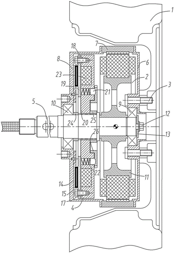
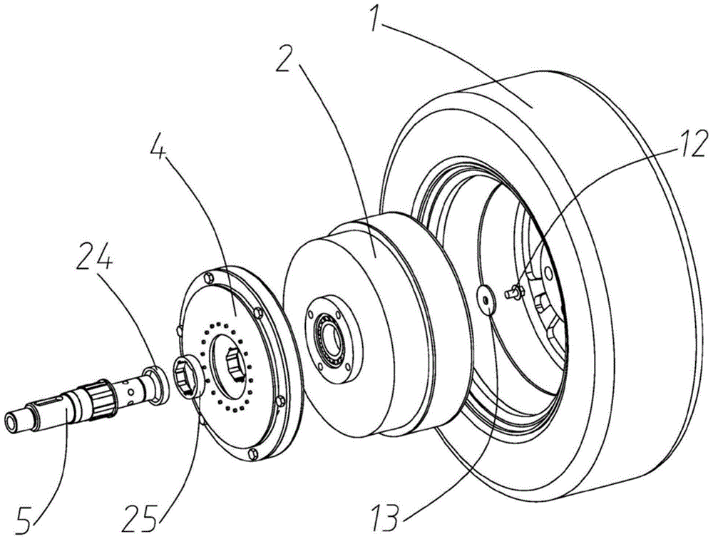
[0028] refer to figure 1 and figure 2 , The integrated electric wheel system with a non-excitation electromagnetic parking brake device has a wheel 1, a hub motor 2, 5 rim bolts 3, an integrated electromagnetic brake 4, a No. 1 bushing 24, and a No. 2 bushing 25.

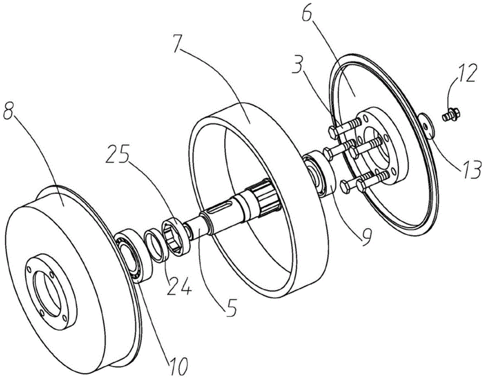
[0029] refer to image 3 , the hub motor 2 has a motor shaft 5, an outer shell of the hub motor 6, an annular shell of the hub motor with permanent magnets embedded in the inner wall 7, an inner shell of the hub motor 8, a tapered roller bearing outside the motor 9, and a tapered roller inside the motor Bearing 10, hub motor stator assembly 11, shaft end bolt 12, shaft end retaining ring 13.

[0030] refer to Figure 4 5, the integrated electromagnetic brake 4...


PUM


Abstract

The invention discloses an integrated electric wheel system with an excitation-free electromagnetic parking braking device, and aims to solve the problem of complex structure of the existing electromagnetic parking braking system. The integrated electric wheel system comprises a wheel, a wheel hub motor, an integrated electromagnetic brake, a No. 1 shaft sleeve and a No.2 shaft sleeve, wherein the integrated electromagnetic brake is integrated in the shell of the wheel hub motor, the integrated electromagnetic brake and a stator assembly of the wheel hub motor are sleeved on a motor shaft in sequence, the rotor part of the integrated electromagnetic brake is fixedly connected with a shell on the inner side of the wheel hub motor, the stator part of the integrated electromagnetic brake and the motor shaft are in splined joint, and a shell on the outer side of the wheel hub motor is fixedly connected with the wheel through rim bolts; the No. 1 shaft sleeve is hollowly sleeved on the motor shaft and is located between the rotor part of the integrated electromagnetic brake and the motor shaft, one end of the No. 1 shaft sleeve is in contact with a shaft neck of the spline end of the motor shaft, and the No. 2 shaft sleeve is sleeved at the spline of the motor shaft and is located between the stator part of the integrated electromagnetic brake and the motor shaft.

Description

technical field [0001] The invention relates to an electric wheel system, in particular to an integrated electric wheel system with a non-excitation electromagnetic parking brake device. Background technique [0002] With the gradual maturity and industrialization of hybrid vehicle technology, the hub motor technology that can be directly arranged in the rim to drive the wheel is also constantly developing and improving. The current in-wheel motor technology mainly involves the improvement of motor performance and coordinated control with the vehicle, but does not involve the design and research of the electric wheel parking brake system. [0003] Large-scale industrial motors and machine tools use electromagnetic brakes to ensure timely parking and accurate braking when they are working. They are divided into excited electromagnetic brakes and non-excited electromagnetic brakes. The main difference is whether the electromagnetic brake is energized when the brake is engaged....

Claims


Application Information

Patent Timeline
Patent Type & Authority Patents(China)
IPC IPC(8): F16D65/22F16D121/20
Inventor 王军年孙文王庆年闫佳伟孙杰魏武李修森付铁军
Owner JILIN UNIV
Why Eureka
Try Eureka