Thermal protection plate

A heat protection and cover plate technology, which is applied in the direction of thin plate connection, aerospace vehicle heat protection devices, nuts, etc., can solve the problems of thermal stress fatigue damage, poor overheating capacity, large metal thermal expansion coefficient, etc., and achieve high-rise inter-layer shear strength , Excellent thermal insulation performance, good interface performance

Active Publication Date: 2019-12-31
GONG YI VAN-RES INNOVATION COMPOSITE MATERIAL CO LTD
View PDF10 Cites 12 Cited by
  • Summary
  • Abstract
  • Description
  • Claims
  • Application Information

AI Technical Summary

Problems solved by technology

Ablation and heat protection, its mechanism is to use the mass injection effect of the gasification product of the heat-resistant material pyrolyzed at high temperature to the boundary to dissipate heat; its biggest advantage is that it is safe and reliable, and has a strong ability to adapt to external heating changes, and can Withstands high heat flow; disadvantages are single use and ablative deformation
Metal thermal protection system is currently the most commonly used thermal protection structure. However, in addition to poor overheating capacity, thermal expansion and deformation of the metal cover plate cause the surface layer to change from laminar flow to turbulent flow prematurely, and the design and manufacturing process is complicated, and it is difficult to inspect and In addition to quality monitoring, there is also the problem of adhesion stability of non-catalytic coatings. In addition, metals have a large thermal expansion coefficient. When subjected to large temperature gradients, thermal stress fatigue damage may occur

Method used


Image

  • Thermal protection plate
  • Thermal protection plate
  • Thermal protection plate

Examples


Embodiment 1

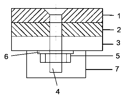
[0028] Such as figure 1 As shown, a heat protection plate includes a cover plate 1, a heat insulating layer 2, and an inner panel 3 from outside to inside in sequence. The outer surface of the cover plate 1 is provided with a SiC coating (not shown), and the cover plate 1 Bolts 4 are installed through the direction of the inner panel 3, and the ends of the bolts 4 extend out of the inner wall of the inner panel 3 and are fixed with nuts 5, and a spring washer 6 is arranged between the inner panel 3 and the nut 5; on the inner wall of the inner panel 3, bolts 4 An airgel heat shield 7 is provided on the outer periphery of the position where the nut 5 is located, and the airgel heat shield 7 and the inner panel 3 are bonded with an inorganic high-temperature adhesive with a heat-resistant temperature not lower than 1000 °C;

[0029] Wherein, the cover plate 1 is a woven structure carbon fiber reinforced ceramic matrix composite material cover plate; the heat insulation layer 2 i...

Embodiment 2

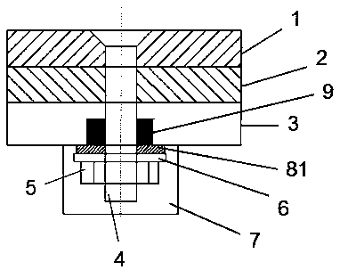
[0031] Such as figure 2 As shown, a heat protection plate includes a cover plate 1, a heat insulating layer 2, and an inner panel 3 from outside to inside in sequence. The outer surface of the cover plate 1 is provided with a SiC coating (not shown), and the cover plate 1 Bolts 4 are provided through the direction of the inner panel 3, the ends of the bolts 4 extend out of the inner wall of the inner panel 3 and are fixed with nuts 5, and the inner wall of the inner panel 3 is provided with airgel heat insulation on the outer periphery where the bolts 4 and nuts 5 are located cover 7, the airgel heat shield 7 and the inner panel 3 are bonded with an inorganic high-temperature adhesive with a heat-resistant temperature not lower than 1000 ° C; the bolt 4 between the inner panel 3 and the nut 5 is sleeved with a first air The gel heat insulation pad 81, the spring washer 6 is arranged between the first airgel heat insulation pad 81 and the nut 5; the bolt 4 located inside the inn...

Embodiment 3

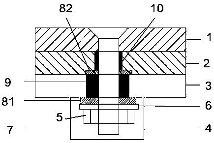
[0034] Such as image 3 As shown, a heat protection plate includes a cover plate 1, a heat insulating layer 2, and an inner panel 3 from outside to inside in sequence. The outer surface of the cover plate 1 is provided with a SiC coating (not shown), and the cover plate 1 Bolts 4 are provided through the direction of the inner panel 3, the ends of the bolts 4 extend out of the inner wall of the inner panel 3 and are fixed with nuts 5, and the inner wall of the inner panel 3 is provided with airgel heat insulation on the outer periphery where the bolts 4 and nuts 5 are located cover 7, the airgel heat shield 7 and the inner panel 3 are bonded with an inorganic high-temperature adhesive with a heat-resistant temperature not lower than 1000 ° C; the bolt 4 between the inner panel 3 and the nut 5 is sleeved with a first air A gel heat insulating pad 81, a spring washer 6 is arranged between the first airgel heat insulating pad 81 and the nut 5; an airgel heat insulating ring 9 is ...


PUM

PropertyMeasurementUnit
thermal resistanceaaaaaaaaaa

Abstract

The invention belongs to the technical field of thermal protection systems, and discloses a thermal protection plate. The thermal protection plate sequentially comprises a cover plate, a heat insulation layer and an inner panel from outside to inside, a bolt is arranged in the direction from the cover plate to the inner panel in a penetrating mode, and the tail end of the bolt extends out of the inner wall of the inner panel and is fixed through a nut; an aerogel heat shield is arranged on the periphery of the positions, where the bolt and the nut are located, of the inner wall of the inner panel; the cover plate is a carbon fiber reinforced ceramic based composite material cover plate; the heat insulation layer is an aerogel felt layer; the inner panel is a resin-based composite materialinner panel; the bolt is a carbon fiber reinforced ceramic based composite material bolt, and the nut is a carbon fiber reinforced ceramic matrix composite material nut. The thermal protection plate is excellent in performance and can meet the requirement that the surface temperature of an aircraft is within the range of 900 DEG C or below.

Description

technical field [0001] The invention belongs to the technical field of heat protection systems, and in particular relates to a heat protection board. Background technique [0002] The thermal protection system (Thermal Protection System, TPS) is a structure used to protect space vehicles from burning and overheating in an aerodynamic heating environment. The use of aircraft such as launch vehicles plays an important role, and its performance and reliability are one of the decisive factors for the advancement and reliability of related power systems and aircraft. So far, there are two types of thermal protection systems: ablative thermal protection systems and reusable thermal protection systems. Ablation and heat protection, its mechanism is to use the mass injection effect of the gasification product of the heat-resistant material pyrolyzed at high temperature to the boundary to dissipate heat; its biggest advantage is that it is safe and reliable, and has a strong ability...

Claims


Application Information

Patent Timeline
Patent Type & Authority Applications(China)
IPC IPC(8): B32B9/00B32B9/04B32B27/38B32B27/20B32B27/06B32B3/08B32B33/00B64G1/58F16B5/02F16B33/00F16B43/00
CPCB32B9/005B32B9/00B32B9/04B32B9/045B32B27/38B32B27/20B32B3/08B32B33/00B64G1/58F16B5/025F16B33/004F16B43/001B32B2262/106B32B2262/101B32B2255/20B32B2307/304
Inventor 姚栋嘉吴恒刘喜宗张东生邓伟吕多军张相国王征
Owner GONG YI VAN-RES INNOVATION COMPOSITE MATERIAL CO LTD
Why Eureka
Try Eureka