
Method for emergency braking of aircraft

A technology of emergency braking and aircraft, applied in the direction of aircraft braking arrangements, brakes, brake components, etc., can solve problems such as long time

Active Publication Date: 2019-12-24
SAFRAN LANDING SYSTEMS
View PDF15 Cites 0 Cited by
  • Summary
  • Abstract
  • Description
  • Claims
  • Application Information

AI Technical Summary

Problems solved by technology

However, mechanical connections via cables, pulleys, linkages take considerable time to install, require multiple supports in the structure of the aircraft, and lead to regular maintenance actions (verification, tension adjustment, lubrication, ...)

Method used


Image

  • Method for emergency braking of aircraft
  • Method for emergency braking of aircraft
  • Method for emergency braking of aircraft

Examples


Embodiment Construction

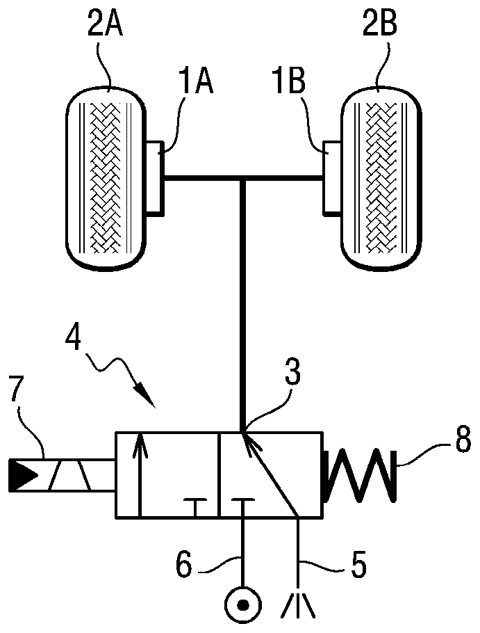
[0018] figure 1 A hydraulic circuit suitable for implementing the emergency braking of the present invention is shown. This emergency brake circuit is an addition to the main brake circuit, not shown. In this example, the aircraft has two brakes 1A and 1B associated with brake wheels 2A and 2B with brakes connected to outlet port 3 of a two-state slide valve 4 which Valve 4 has a stable static state (such as figure 1 shown) and the active state, in which the slider of the valve 4 connects the outlet port 3 to the return port 5 in the rest state, and in the active state, the slider of the valve 4 connects the outlet port 3 to the inlet port 6. The coil 7 forces the slide of the valve 4 to assume the active state when the coil 7 is powered by the control voltage, and the spring 8 returns the slide of the valve 4 to the rest state when the coil 7 is no longer powered.

[0019] According to the invention, the coil 7 is powered such that the pressure delivered to the brakes 1A a...


PUM


Abstract

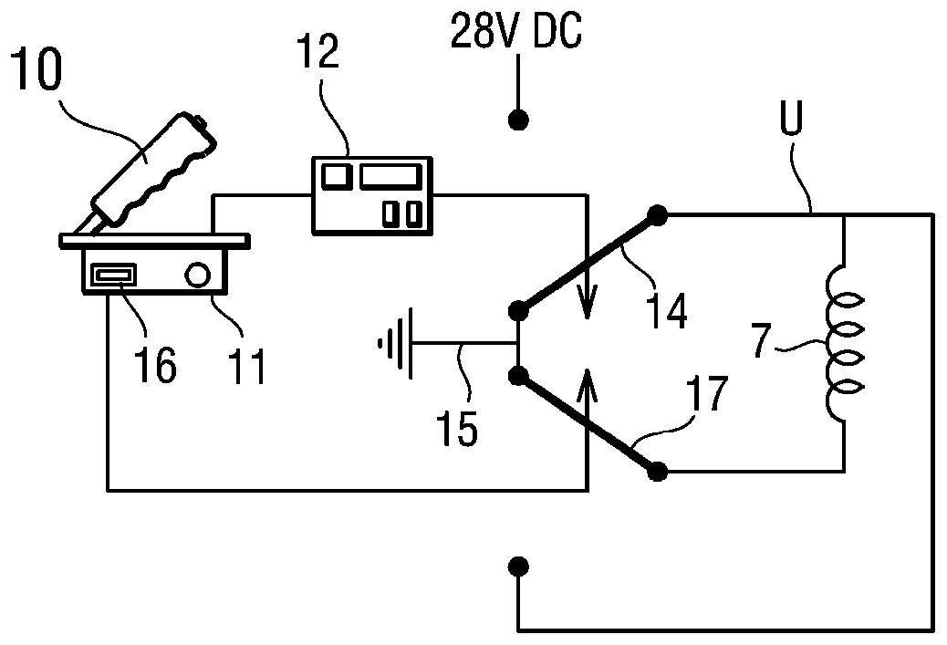
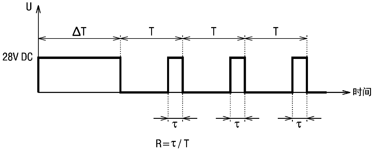
An emergency braking method for an aircraft, comprising using a progressing parking brake controlled by a lever (10) that can be actuated by the pilot between a "0%" position in which the brakes are connected to the return pressure of the aircraft, and a "100%" position in which the brakes are connected to the feed pressure of the aircraft, the lever being blockable in the 100% position in order to provide parking braking when the aircraft is stationary. According to the invention, the emergency braking method is characterized in that it comprises: using a valve having an outlet port connectedto the brakes, a return port, and a feed port, the valve presenting a state connecting the outlet port to the return port and a state connecting the outlet port to the feed port; and controlling thevalve to occupy one or other of those states by pulse width modulation (PWM) having a duty ratio (R) that is a function of the position of the lever in order to deliver the brakes with pressure lyingin the range return pressure to feed pressure, depending on the position of the lever.

Description

technical field [0001] The invention relates to an emergency braking method for an aircraft. Background technique [0002] Aircraft such as large commercial aircraft used to transport passengers are known to comprise a main braking circuit and an emergency braking circuit adapted for use in the event of failure of the main braking circuit. These circuits are completely isolated and each circuit requires a large number of passive hydraulic components such as accumulators, filters and active hydraulic components such as gates, valves and servo valves, which are suitable for specific Brake pressure is delivered proportional to the brake set point determined by the brake computer due to the pilot acting on the brake pedal. In addition to these two circuits, the aircraft is usually equipped with a parking brake adapted to apply and maintain the brakes after the pilot operates the park selector by while the aircraft is stationary, for example by using a bistable valve. The given...

Claims


Application Information

Patent Timeline
Patent Type & Authority Applications(China)
IPC IPC(8): B60T8/17B60T13/68
CPCB60T8/1703B60T13/686B60T13/66B64C25/42B60T7/085B60T2270/402B64C25/44F15B11/16F15B2211/4159F15B2211/427F15B2211/6346
Inventor D·弗兰克J·弗拉瓦尔D·沃林
Owner SAFRAN LANDING SYSTEMS
Learn More