
Car gear shifter

A technology for shifting gears and moving baffles in automobiles, which is applied to components with teeth, transmission control, belts/chains/gears, etc.

Inactive Publication Date: 2017-09-19
CIXI SANHE INTELLIGENT SANITARY WARE CO LTD
View PDF0 Cites 0 Cited by
  • Summary
  • Abstract
  • Description
  • Claims
  • Application Information

AI Technical Summary

Problems solved by technology

In addition, particularly high forces are required to release the parking mechanism
For the traditional shifting mechanism, in order to reduce the driver's wrong shifting operation, a complex hardware structure is used, which is not conducive to simplifying the shifting operation

Method used


Image

  • Car gear shifter
  • Car gear shifter
  • Car gear shifter

Examples


Embodiment Construction

[0017] Below in conjunction with accompanying drawing, this kind of automobile shifter is further described:

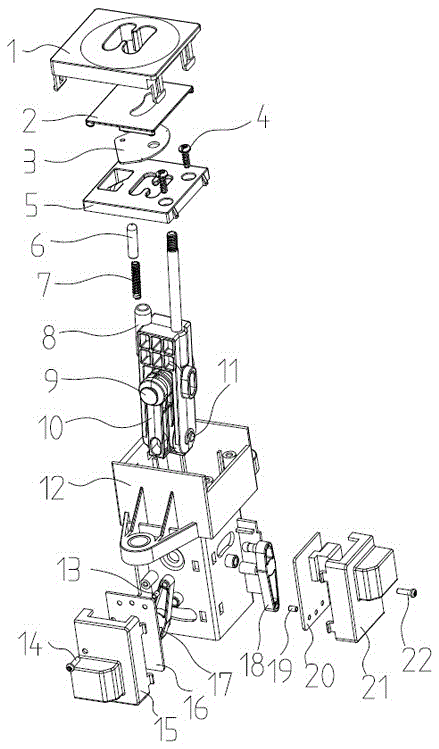
[0018] Such as figure 1 As shown, the shifter includes an upper cover 1, a movable baffle 2, a fan-shaped baffle 3, a fixing screw 4, a cover plate 5, a metal post 6, a spring 7, a large swing arm 8, a large fixed pin 9, and a small swing arm 10 , small fixing pin 11, housing 12, permanent magnet 13, fixing screw 14, circuit board cover 15, circuit board 16, swing lever 17, swing lever 18, permanent magnet 19, circuit board 20, circuit board cover 21, fixing screw twenty two.

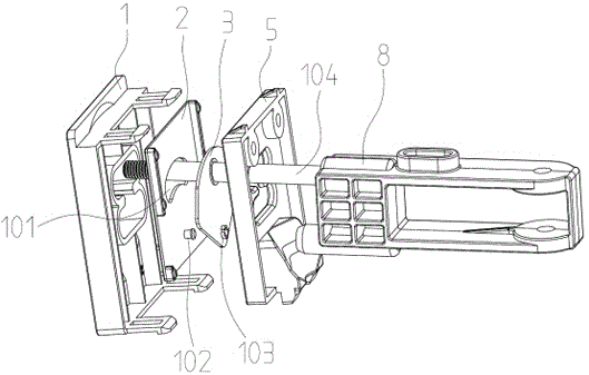
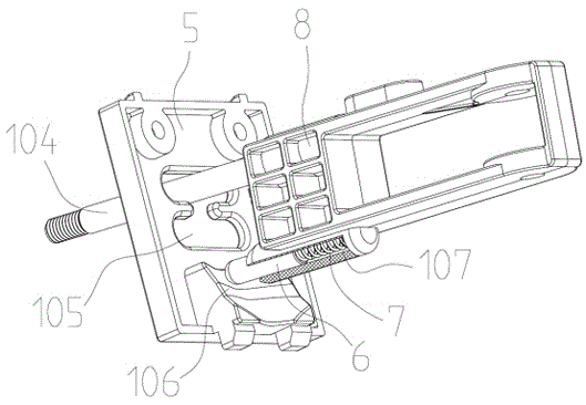
[0019] Such as Figure 2~Figure 7 As shown, the large swing arm 8 and the small swing arm 10 are hinged by the small fixed pin 11, and the large swing arm 8 can swing around the small fixed pin 11. The small swing arm 10 hinges the large swing arm 8 and the small swing arm 10 on the housing 12 through the large fixed pin 9, and the large swing arm 8 and the small swing arm 10 can swing aroun...


PUM


Abstract

An automobile gear shifter, which drives the hinged large swing arm and small swing arm to rotate through the toggle of the shift handle rod. The large swing wall and the small swing arm are respectively connected to a swing rod. The swing rod can pass through the large swing wall. The rotation of the small swing arm and the rotation of the small swing arm is driven by a permanent magnet. The permanent magnets on the two swing levers are respectively attached to a circuit board with three Hall sensors to rotate, and the magnets are aligned to different positions. Hall sensor position to judge the current gear.

Description

technical field [0001] The invention relates to an automobile shifter. Background technique [0002] The role of the shift system is to manipulate the parking mechanism and select forward gear, reverse gear and neutral gear. Traditionally, most shift systems consist of a shift lever in the cab and a shift mechanism in the gearbox. This type of shifting device limits the structural form, shifting operation force, shifting mode, etc. of the shifting lever, and also limits the operability of shifting. For example, for the current shifting lever, whether it is straight or cylindrical, The arrangement order of shift positions is all P, R, N, D. Because the structure of the automatic transmission determines all this. Furthermore, particularly high forces are required to release the parking mechanism. For the traditional shifting mechanism, in order to reduce the driver's wrong shifting operation, a complex hardware structure is used, which is not conducive to simplifying the s...

Claims


Application Information

Patent Timeline
IPC IPC(8): F16H59/02
CPCF16H59/0217F16H59/0278
Inventor 张建和
Owner CIXI SANHE INTELLIGENT SANITARY WARE CO LTD
Learn More