Centrifugal compressor

a centrifugal compressor and compressor technology, applied in the direction of machines/engines, mechanical equipment, liquid fuel engines, etc., can solve the problems of reducing performance (or reducing pressure ratio), and achieve the effect of reducing performance and reducing pressure ratio

Active Publication Date: 2022-01-20
TOYOTA IND CORP
View PDF6 Cites 0 Cited by
  • Summary
  • Abstract
  • Description
  • Claims
  • Application Information

AI Technical Summary

Benefits of technology

[0004]For the impeller of the centrifugal compressor described in Japanese Patent Laid-Open No. 2018-168707, a portion of an air current flowing toward a discharging side along the external radial surface of the hub may collide with a portion of an inner circumferential surface surrounding the through hole that is located downstream of the air current, and accordingly, flow toward the back surface of the impeller through the through hole. This results in reduced performance (or a reduced pressure ratio).

Problems solved by technology

This results in reduced performance (or a reduced pressure ratio).

Method used


Image

  • Centrifugal compressor
  • Centrifugal compressor
  • Centrifugal compressor

Examples


Embodiment Construction

[0012]An embodiment of the present invention will now be described with reference to the drawings. In the figures referred to below, any identical or equivalent member is identically denoted.

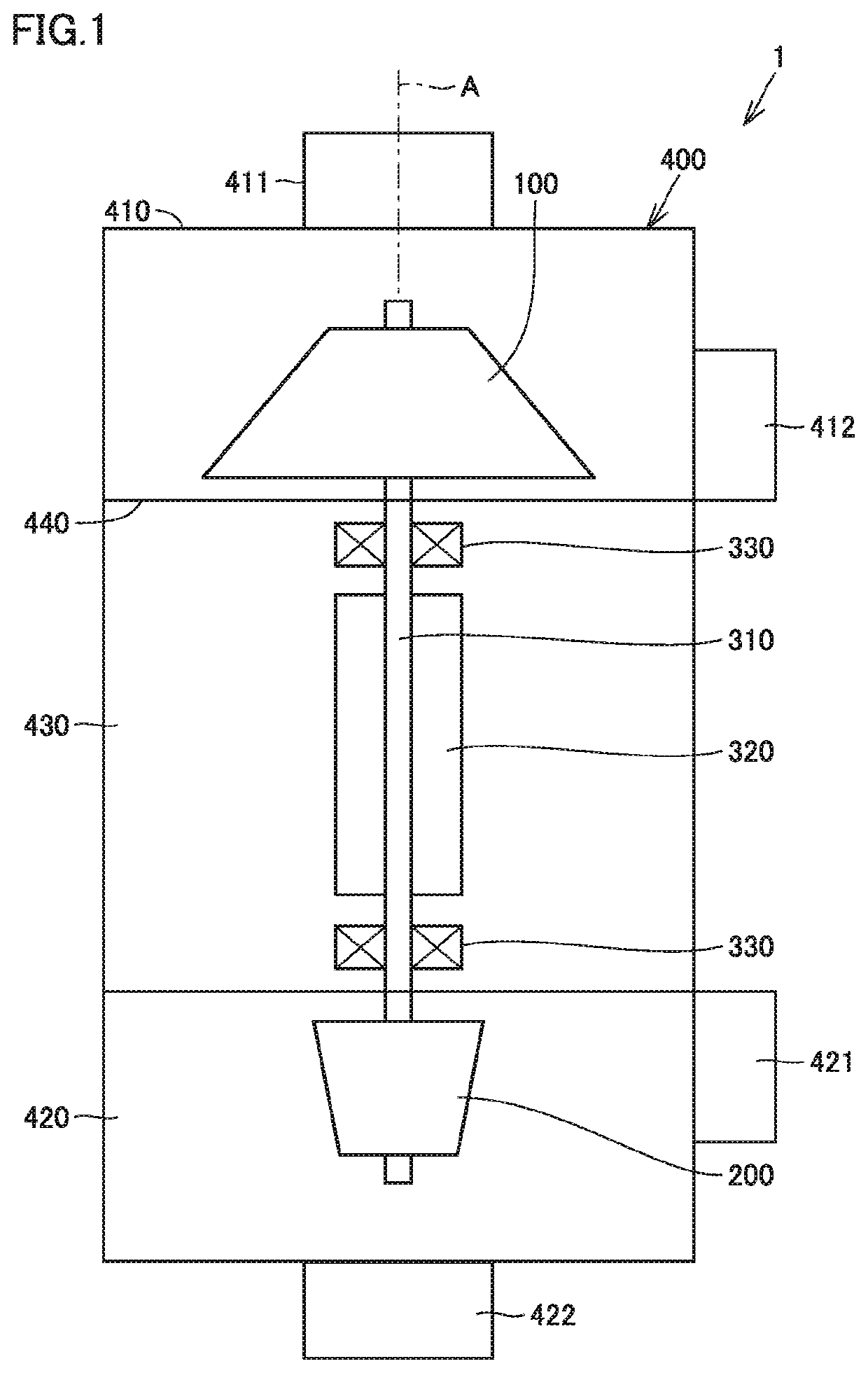
[0013]FIG. 1 is a diagram schematically showing a configuration of a centrifugal compressor according to an embodiment of the present invention. As shown in FIG. 1, the centrifugal compressor 1 includes an impeller 100, a turbine wheel 200, a rotation shaft 310, a motor 320, a bearing 330, and a casing 400.

[0014]The rotation shaft 310 interconnects the impeller 100 and the turbine wheel 200. The rotation shaft 310 is rotationally driven by the motor 320. The rotation shaft 310 is received by the bearing 330. The motor 320 includes a rotor and a stator (not shown).

[0015]The casing 400 houses the impeller 100, the turbine wheel 200, the rotation shaft 310, the motor 320, and the bearing 330. The casing 400 has a compressor housing 410, a turbine housing 420, and a center housing 430.

[0016]The comp...


PUM


Abstract

A centrifugal compressor comprises an impeller including a hub and a plurality of blades. The hub is provided with a through hole. The hub has an external radial surface having an inner external radial surface and an outer external radial surface. The outer external radial surface is formed closer to a back surface than an imaginary curved surface having as a radius a radius of curvature of the inner external radial surface at a radially outer edge thereof.

Description

[0001]This nonprovisional application is based on Japanese Patent Application No. 2020-121242 filed on Jul. 15, 2020 with the Japan Patent Office, the entire contents of which are hereby incorporated by reference.BACKGROUND OF THE INVENTIONField of the Invention[0002]The present invention relates to a centrifugal compressor.Description of the Background Art[0003]For example, Japanese Patent Laid-Open No. 2018-168707 discloses a centrifugal compressor including an impeller. The impeller in the centrifugal compressor has a hub having an external radial surface and a back surface, and a plurality of blades. The hub is provided with a through hole formed therethrough between the external radial surface and the back surface. The through hole thus formed reduces a moment of inertia of the impeller and a thrust load acting on the impeller.SUMMARY OF THE INVENTION[0004]For the impeller of the centrifugal compressor described in Japanese Patent Laid-Open No. 2018-168707, a portion of an air ...

Claims


Application Information

Patent Timeline
Patent Type & Authority Applications(United States)
IPC IPC(8): F04D29/28F04D29/30F04D17/10F04D29/043
CPCF04D29/284F04D29/043F04D17/10F04D29/30F04D29/681F04D29/0516F05D2250/191F05D2240/30F05D2210/12
Inventor UMEYAMA, RYONAKANE, YOSHIYUKI
Owner TOYOTA IND CORP
Why Eureka
Try Eureka