Gas safety valve and gas supply line

a safety valve and gas supply technology, applied in the direction of valve housings, functional valve types, mechanical devices, etc., can solve the problems of limited space for gas fittings and undesirable gas supply reconnections, and achieve the effect of minimising the risk of gas safety valves and reducing the ingress of debris

Active Publication Date: 2022-01-27
GAS STOP EURO BV
View PDF0 Cites 0 Cited by
  • Summary
  • Abstract
  • Description
  • Claims
  • Application Information

AI Technical Summary

Benefits of technology

[0013]To minimise ingress of debris when the side inlet fitting is not in use, the side inlet fitting may comprise a cap which can be unscrewed from the side inlet fitting when the side inlet port is to be coupled to a second gas source. The cap may be retained by a flexible retainer to the side inlet fitting to prevent loss of the cap when it has been unscrewed from the side inlet fitting.
[0014]The side inlet fitting (and side inlet axis) may extend at right angles to the longitudinal axis. In particular, the side inlet fitting (and side inlet axis) may extend from the valve body in a 270° direction when the gas safety valve is viewed from above the pressure gauge with the body inlet port extending in a 0° direction and the body outlet port extending in a 180° direction. Such a right-handed projection allows the gas safety valve to be connected in existing gas supply lines of some mobile homes, for example. The right-angled arrangement also helps to minimise risk of the gas safety valve from unscrewing from the respective gas supplies. The side inlet fitting (and side inlet axis) may also be arranged at right angles to the stem axis.

Problems solved by technology

This might be desirable for a mobile home, caravan or boat, where it is usual to carry a spare gas canister and it would be undesirable to have to reconnect a gas supply in the event one ran out of gas.
In such applications, space for gas fittings can be limited.

Method used


Image

  • Gas safety valve and gas supply line
  • Gas safety valve and gas supply line
  • Gas safety valve and gas supply line

Examples


Embodiment Construction

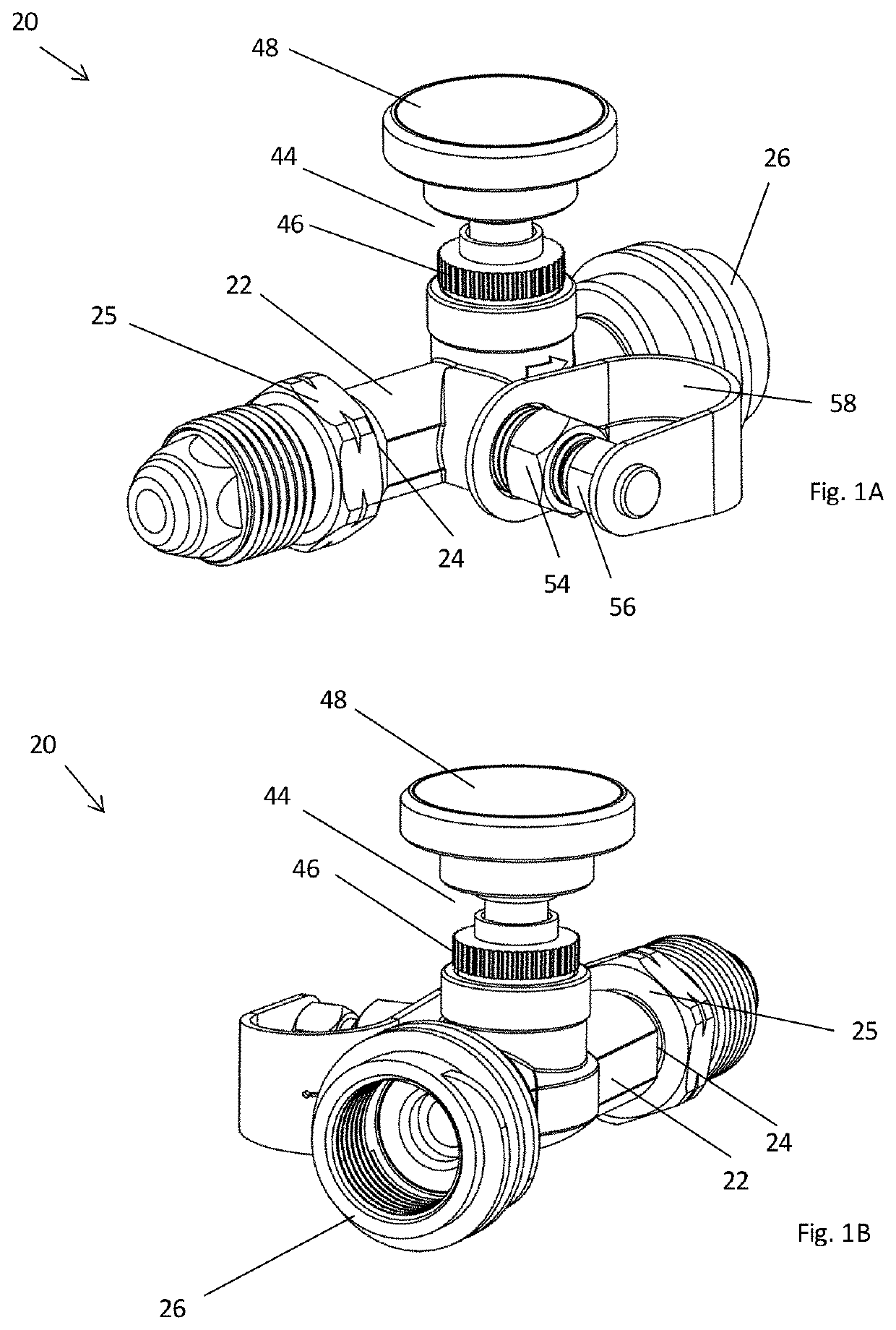
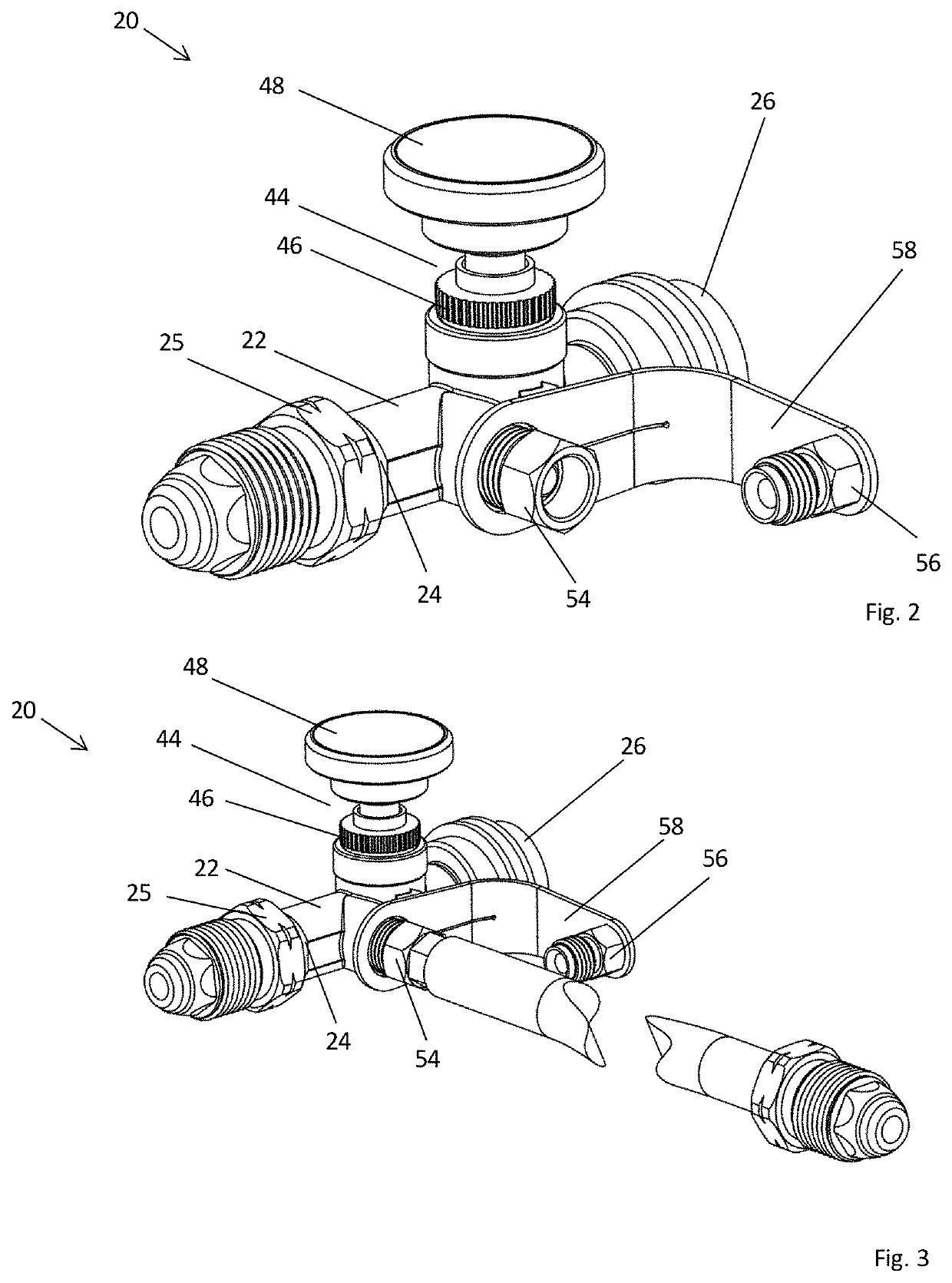
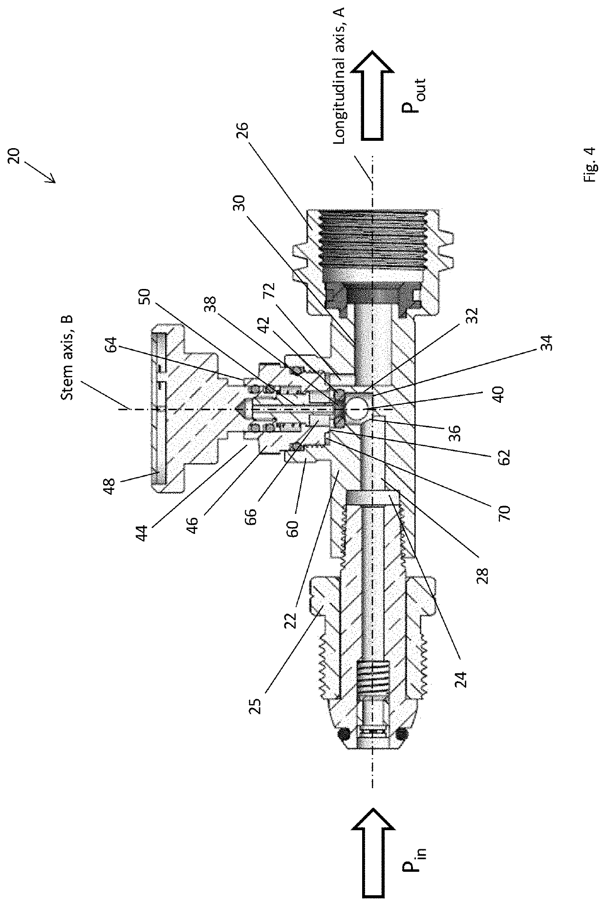
[0039]FIG. 1A is a perspective view of a gas safety valve 20. The gas safety valve 20 comprises a valve body 22 extending along a longitudinal axis A with a body inlet port 24 located at one end of the valve body 22 and a body outlet port 26 located at the opposite end of the valve body 22. The longitudinal axis A extends between the body inlet port 24 and the body outlet port 26. The valve body 22 may comprise a single piece casting which has been machined to provide bores and screw threads to direct a flow of gas and to connect with other components. FIG. 1B is a perspective view of the gas safety valve 20 from the opposite direction.

[0040]The gas safety valve 20 may further comprise a valve body inlet fitting 25 mounted in the body inlet port 24. The gas safety valve 20 may be supplied with the valve body inlet fitting 25 already provided and mounted in the body inlet port 24. The valve body inlet fitting 25 may be provided with a non-return valve and a coupling end, wherein the ...


PUM


Abstract

A gas safety valve for controlling a gas flow includes a valve body providing a body inlet port for coupling to a first gas supply and a body outlet port for coupling to an appliance, the valve body extending along a longitudinal axis between the body inlet port and the body outlet port, the valve body further providing an inlet bore extending downstream from the body inlet port, and an outlet bore extending to the body outlet port. A valve has a valve chamber having a valve inlet and a valve outlet, a ball located within the valve chamber and a valve seat provided at the valve outlet such that the ball is retained in the valve chamber upstream of the valve seat. The valve body includes an internal junction positioned upstream of the valve inlet, and a side inlet port.

Description

FIELD OF THE INVENTION[0001]The present disclosure relates to a gas safety valve, in particular a gas safety valve comprising a side inlet port for allowing coupling of a second gas supply. It also relates to a gas supply line incorporating such a gas safety valve and a method of supplying gas to an appliance.BACKGROUND OF THE INVENTION[0002]Gas safety valves are known and are used as safety devices in gas supply lines between gas supplies and appliances in order to shut off the supply of gas to the appliance or appliances in the event a leak develops downstream of the gas safety valve.[0003]Gas safety valves may have a valve comprising a ball, which is retained in a valve chamber. Gas enters the valve chamber through a valve inlet and exits through a valve outlet as it passes through the gas safety valve. The size and weight of the ball can be selected so that the ball, when the gas safety valve is in normal use, rests away from a valve seat to allow a supply of gas to exit to the ...

Claims


Application Information

Patent Timeline
Patent Type & Authority Applications(United States)
IPC IPC(8): F16K17/28F16K15/04F16K37/00
CPCF16K17/285F16K37/0091F16K15/04F16K27/0245F16K11/105F16K37/0066F16K17/205
Inventor LEWIS, CHRIS ANDREW
Owner GAS STOP EURO BV
Why Eureka
Try Eureka