
Method for calibrating on-line and with forgetting factor a direct neural interface with penalised multivariate regression

a multi-variate regression and direct neural interface technology, applied in the field of direct neural interfaces, can solve the problems of inability to implement the calibration method using a penalised multi-path regression on-line, the validity of the predictive model is however limited in time, and the manipulation of a considerable amount of data on-lin

Pending Publication Date: 2022-04-14
COMMISSARIAT A LENERGIE ATOMIQUE ET AUX ENERGIES ALTERNATIVES
View PDF0 Cites 0 Cited by
  • Summary
  • Abstract
  • Description
  • Claims
  • Application Information

AI Technical Summary

Benefits of technology

The patent text describes a method for minimizing a penalty metric associated with a projector. The method involves a step of minimizing the penalty over a set of indices that correspond to the penalizable elements of the projector. The method uses a matrix and a set of coefficients to determine the penalty. The technical effect of this invention is to provide an efficient way to minimize the penalty associated with a projector, which can improve the overall performance of the projector.

Problems solved by technology

The validity of the predictive model is however limited in time on account of the non-stationarity of the neural signals.
However, these on-line calibration methods may require the manipulation of a considerable amount of data resulting from the juxtaposition of data from prior calibration steps and those from a new calibration step.
However, such a calibration method using a penalised multipath regression cannot be implemented on-line on account of the considerable amount of calculations that it requires.

Method used


Image

  • Method for calibrating on-line and with forgetting factor a direct neural interface with penalised multivariate regression
  • Method for calibrating on-line and with forgetting factor a direct neural interface with penalised multivariate regression
  • Method for calibrating on-line and with forgetting factor a direct neural interface with penalised multivariate regression

Examples


Embodiment Construction

[0014]The present invention is defined by a method for calibrating on-line a direct neural interface intended to receive a plurality of electrophysiological signals during a plurality of observation windows associated with observation times, to form an input tensor and to deduce therefrom, by means of a predictive model, an output tensor providing command signals intended to command one or more effectors, said calibration is carried out during a plurality of calibration steps, each calibration step u being carried out from input calibration data, represented by an input calibration tensor, Xu∈□(I1× . . . ×IN), and from output calibration data represented by an output calibration tensor Yu∈□(J1× . . . ×JM), said calibration step implementing a REW-NPLS regression comprising:

[0015]the calculation of a covariance tensor XXu from a covariance tensor XXu−1 obtained during a preceding calibration step and the tensor Xu, as well as the calculation of a cross covariance tensor XYu from a cr...


PUM


Abstract

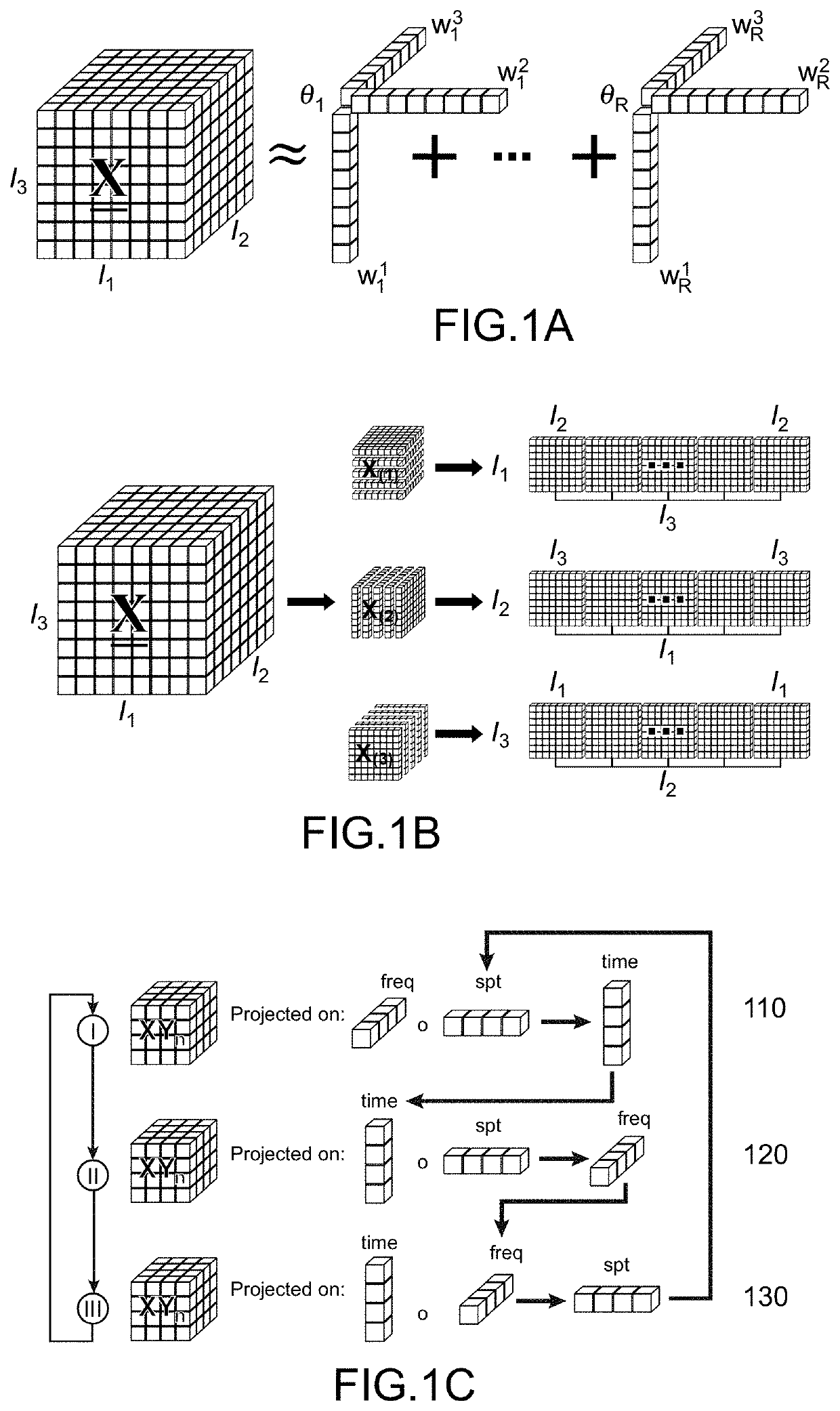
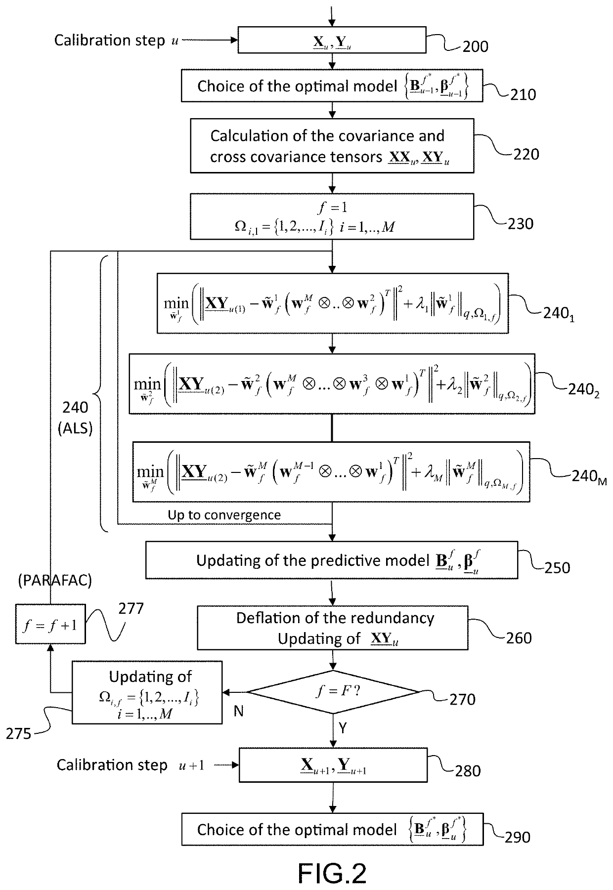
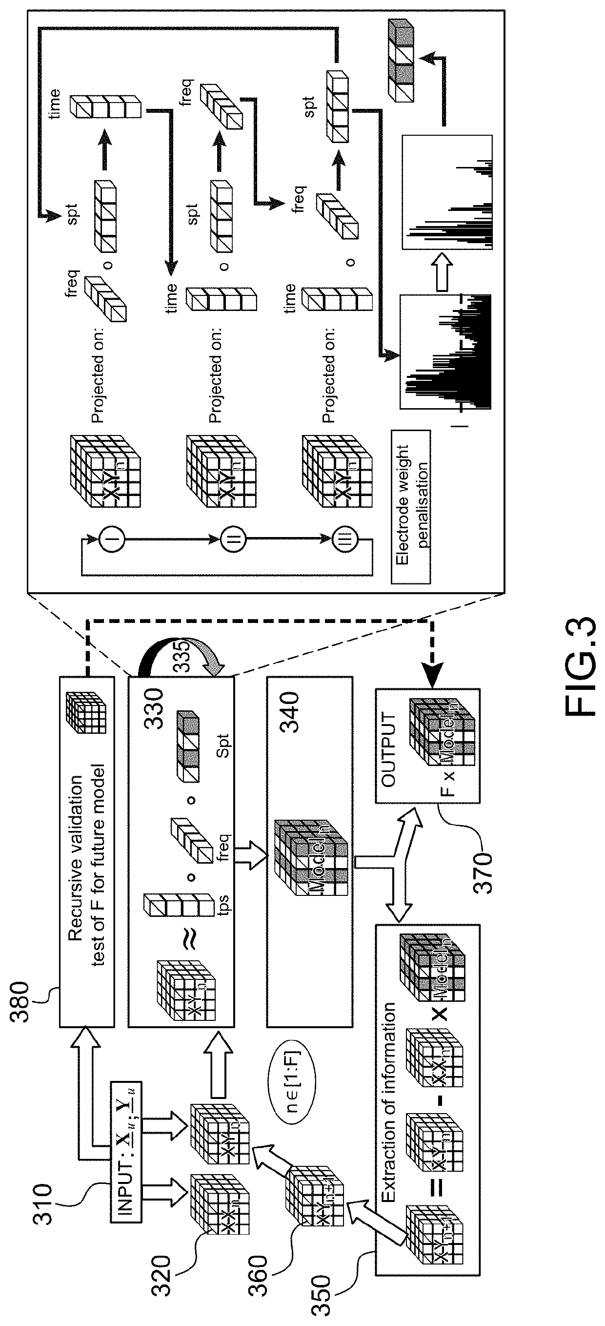
The present invention relates to a method for calibrating on-line a direct neural interface implementing a REW-NPLS regression between an output calibration tensor and an input calibration tensor. The REW-NPLS regression comprises a PARAFAC iterative decomposition of the cross covariance tensor between the input calibration tensor and the output calibration tensor, each PARAFAC iteration comprising a sequence of M elementary steps (2401, 2401, . . . 240M) of minimisation of a metric according to the alternating least squares method, each elementary minimisation step relating to a projector and considering the others as constant, said metric comprising a penalisation term that is a function of the norm of this projector, the elements of this projector not being subjected to a penalisation during a PARAFAC iteration f not being penalisable during following PARAFAC iterations. Said calibration method makes it possible to obtain a predictive model of which the non-zero coefficients are sparse blockwise.

Description

TECHNICAL FIELD[0001]The present invention relates to the field of direct neural interfaces, also called BCI (Brain Computer Interfaces) or BMI (Brain Machine Interfaces). It is notably applied to the direct neural command of a machine, such as an exoskeleton or a computer.PRIOR ART[0002]Direct neural interfaces use the electrophysiological signals emitted by the cerebral cortex to elaborate a command signal. These neural interfaces have been the subject of numerous research notably with the aim of restoring a motor function to a paraplegic or tetraplegic subject using a motorised prothesis or orthosis.[0003]Neural interfaces may be of invasive or non-invasive nature. Invasive neural interfaces use intracortical electrodes (that is to say implanted in the cortex) or cortical electrodes (arranged on the surface of the cortex) collecting in this latter case electrocorticographic (EcoG) signals. Non-invasive neural interfaces use electrodes placed on the scalp to collect electrocephalo...

Claims


Application Information

Patent Timeline
IPC IPC(8): A61B5/279G06K9/64G06F3/01
CPCA61B5/279A61B2560/0228G06F3/015G06K9/64G06F17/16G06V10/75
Inventor MOLY, ALEXANDREAKSENOVA, TETIANAAKSENOV, ALEXANDRE
Owner COMMISSARIAT A LENERGIE ATOMIQUE ET AUX ENERGIES ALTERNATIVES
Learn More