
Support structure for a conveyor system

a technology of conveyor system and support structure, which is applied in the direction of mechanical conveyors, packaging, instruments, etc., can solve the problems of poor product quality, false rejection of good products, and vibration of any monitoring sensor, so as to prevent the ingress of liquid, reduce vibration, and reduce the effect of ingress of water

Pending Publication Date: 2020-09-24
ILLINOIS TOOL WORKS INC
View PDF6 Cites 0 Cited by
  • Summary
  • Abstract
  • Description
  • Claims
  • Application Information

AI Technical Summary

Benefits of technology

The present invention provides a solution to suppress vibrations caused by a transport conveyor system by mounting the conveyor onto an externally mounted support column that dampens the vibrations and minimizes erroneous weight measurements. The support column is made of a resilient material, such as plastic or rubber. Additionally, the invention provides a removable waterproof outer jacket for the motor casing that seals the motor against the ingress of water even under the action of a high pressure water hose. The jacket is composed of a resilient material that enables the jacket to stretch around the motor casing as a snug fit.

Problems solved by technology

In any of these dynamic monitoring processes on a conveyor system, vibrations of any of the monitoring sensors can adversely affect the monitoring process of a product.
Specifically, vibrations can lead to imprecise measurements of the weight—particularly if the vibrations cause reverberations in the weight transducer, e.g. a load cell.
Such vibrations can lead to good products being falsely rejected.
Also, the pushing device and the motors for driving the conveyor apparatus provide further vibrations when in operation.
As a result, the support structure requires extensive use of specialist equipment and work force, e.g. specialist welders, to assemble the different fixtures to the support structure, not least to handle the potential chemical hazard in the use of resins or ballast material to fill the support beam.
Not only can this cause a bottleneck in the production line resulting in significant downtime, but it also adds costs to the manufacturing process of the inspection apparatus.
This results in a very cluttered support structure with exposed cabling having areas that are not easily accessible or which require components to be dismantled before they can be accessed.
Further to the need for a reduction of vibrations, another challenging problem with conveyor systems is the difficulty in maintaining high levels of hygiene, particularly in the case of the pharmaceutical and food industries.
Such spillages can include liquids from animal products, dairy products etc, which are a potential source of harmful bacteria if not cleaned.
This leads to considerable down-time and causes an overall lower efficiency of monitoring the products, especially when there is a change in a product type on a production line.
Thus the disclosed apparatus suffers from the need to fill parts of the support frame with ballast material in order to suppress vibrations.
The support frame is also crowded with fixtures and exposed cabling making the task of cleaning the weigh conveyor very time consuming and cumbersome.

Method used


Image

  • Support structure for a conveyor system
  • Support structure for a conveyor system
  • Support structure for a conveyor system

Examples


Embodiment Construction

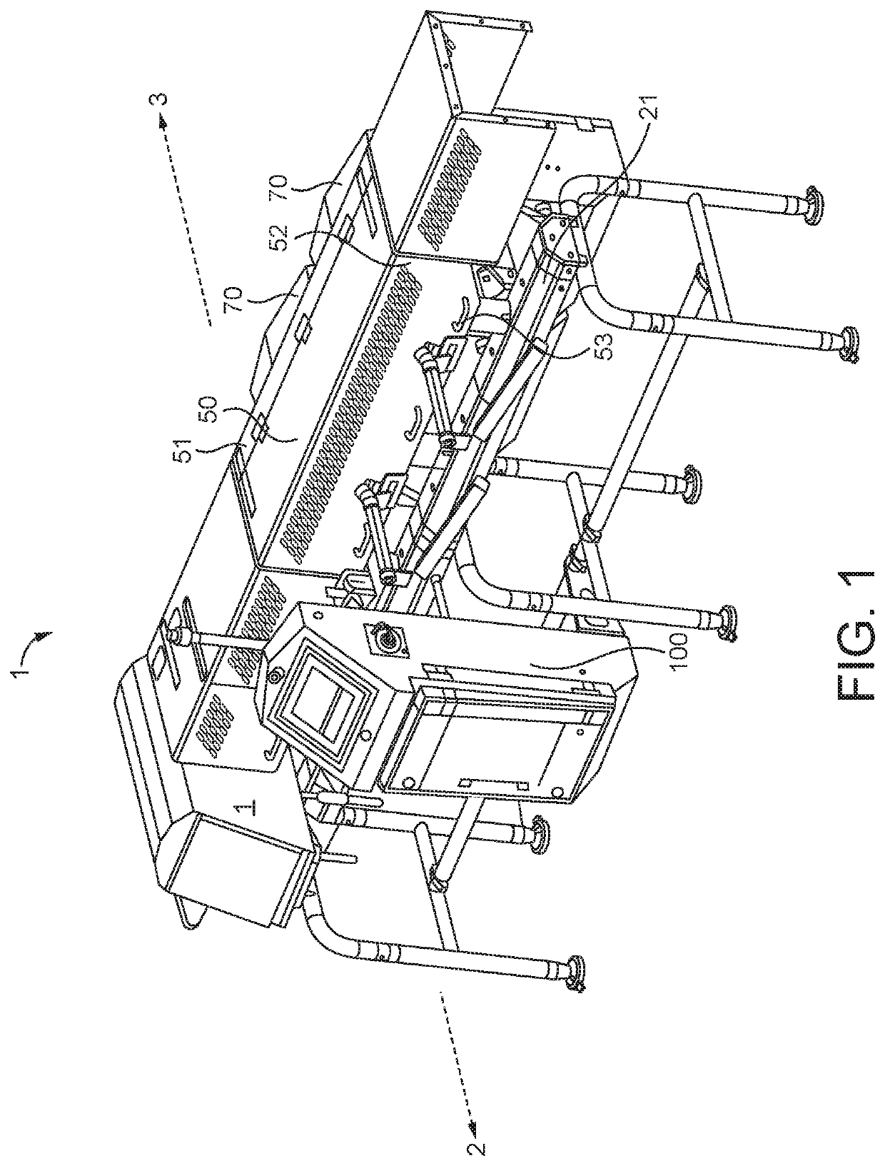
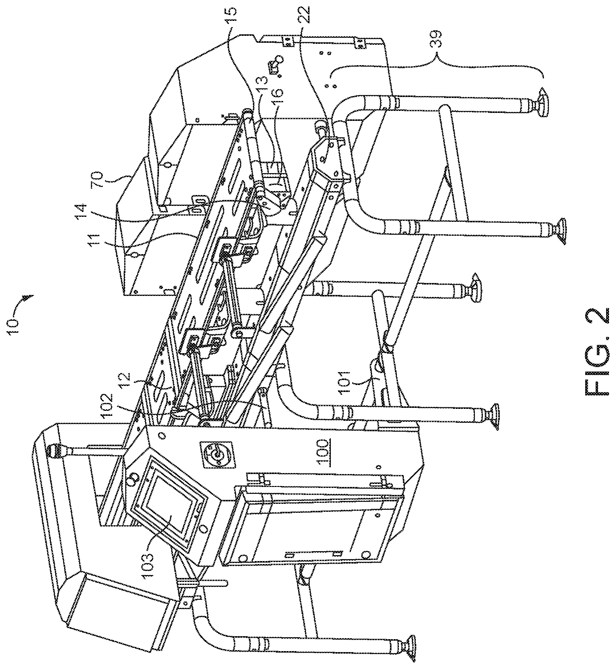
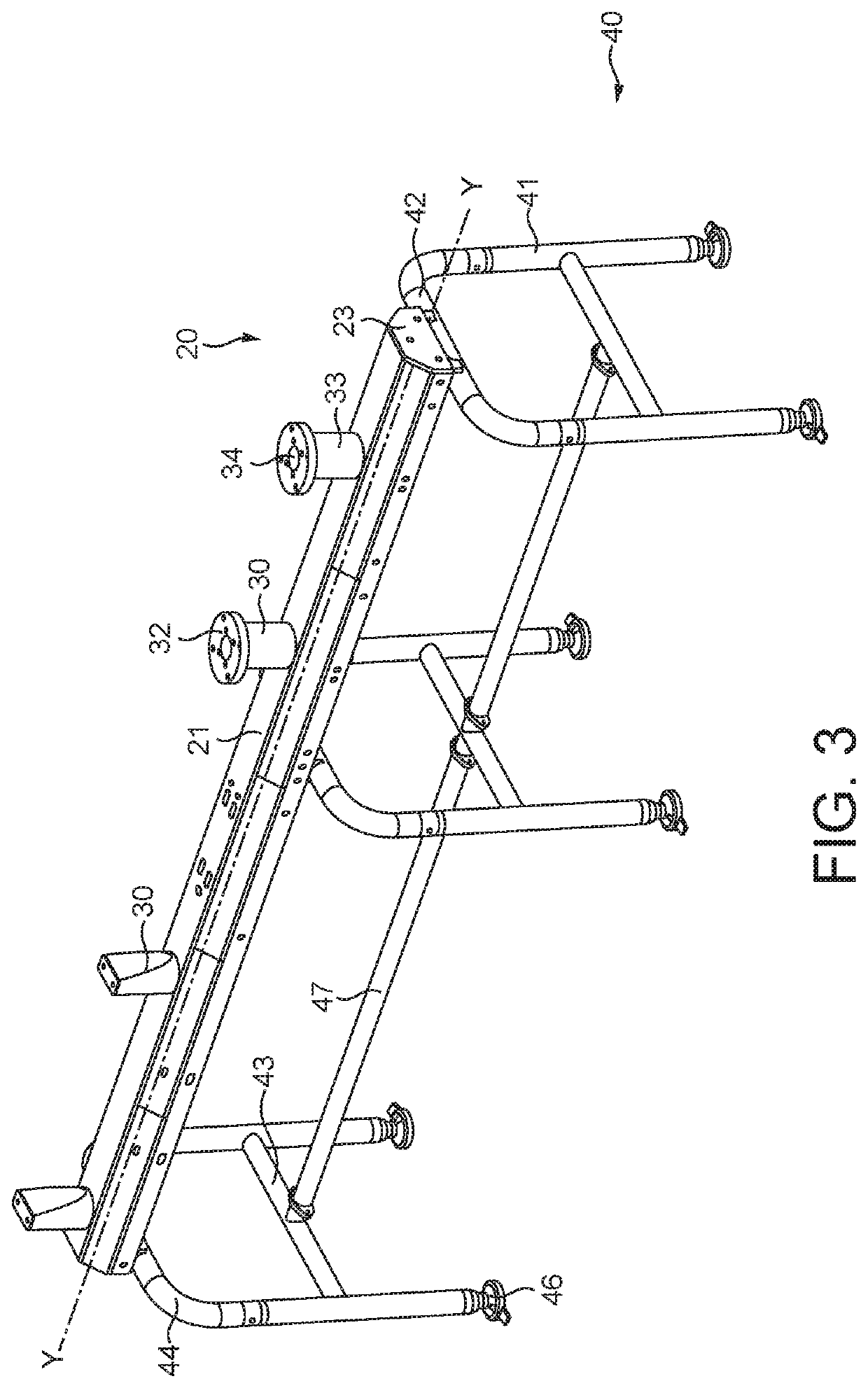
[0044]FIG. 1 shows a perspective view of a product inspection apparatus 1 comprising a conveyor system for transporting products. The product inspection apparatus 1 has a forward side 2 and an aft side 3. Now referring to FIG. 2, products to be tested are transported by the conveyor system 10, said conveyor system comprises at least one conveyor bed 11 (i.e. a support surface over which the top run of the at least one conveyor or belt runs (mostly hidden in the figures)), at least one conveyor 12, and at least one electrical motor 13 to drive the conveyor system, via at least one belt 14 and a corresponding powered roller 15 around which the belt 12 is trained. As shown in FIG. 8, the conveyor system comprises a weigh conveyor 18, said weigh conveyor is supported by a load detector for detecting the weight of products transported on the conveyor system, and a transport conveyor adjacent the weigh conveyor. The transport conveyor comprises an infeed conveyor 17 and an exit conveyor 1...


PUM


Abstract

A product inspection apparatus includes a conveyor system for transporting items. The conveyor system includes a weigh conveyor with a load detector for detecting the weight of items transported on the conveyor system and a transport conveyor adjacent the weigh conveyor. The apparatus also includes a support structure with a support beam. The transport conveyor is mounted to the support beam by at least one support column externally mounted to the support beam such that vibrations are suppressed by the at least one externally mounted support column.

Description

FIELD OF THE INVENTION[0001]The present invention relates to the field of support structures or frames for product inspection apparatus. More particularly, the invention concerns a support structure or frame for supporting a checkweigher, optionally together with other product inspection equipment such as a metal detector and / or X-ray machine, in a conveyor system of a product inspection apparatus.BACKGROUND[0002]Food products and packaged commodities are rigorously inspected to make sure that they comply with applicable standards with regards to weight, hygiene or presence of contamination etc. For example, in the European Union the accuracy of weight measurements should meet the requirements dictated by the Measuring Instruments Directive (MID). Equivalent legislation concerning accuracy of weight measurements exist in other regions of the world.[0003]To inspect large numbers of products in a production line, they are typically inspected as they are transported by a conveyor appar...

Claims


Application Information

Patent Timeline
Patent Type & Authority Applications(United States)
IPC IPC(8): G01G11/00G01G17/02B65G41/00B65G37/00
CPCB65G2207/20B65G2203/044B65G2201/0217G01G11/003B65G2203/0258B65G41/006G01G17/02B65G37/00
Inventor HIRANI, HITESH R.ALEXANDER, ANDREW T.
Owner ILLINOIS TOOL WORKS INC
Learn More