Roof unit and basic structure of road-bound vehicle

a technology for roof units and vehicles, applied in superstructure subunits, construction, transportation and packaging, etc., can solve the problems of difficult assembly and joining of roofs to base units, poor structural strength, and limited freedom of movement of people or machines in finished vehicle bodies, etc., to achieve the effect of simple manufacturing

Inactive Publication Date: 2009-08-04
ALCAN TECH & MANAGEMENT LTD
View PDF11 Cites 1 Cited by
  • Summary
  • Abstract
  • Description
  • Claims
  • Application Information

AI Technical Summary

Benefits of technology

[0011]The object of the present invention is to propose a process for manufacturing a vehicle body with a roof unit and a base unit or basic structure for a horizontally joined body of a road-bound vehicle, such that the roof unit makes manufacturing simple, and the joining of the roof unit and the basic structure is easy, in particular in conveyor-belt series production.
[0014]The base unit or basic structure may e.g. be in any prefabricated form. Preferred is a base unit—with respect to the interior fittings—such featuring wiring, floor covering, seats, operating elements, instruments etc.—to a large degree prefabricated, in order to minimise further work-steps in the vehicle interior formed by joining the roof and base units or basic structure.
[0032]With the roof units described above it is possible to fabricate the basic structure almost to completion, whereby the roof initially remains open, and the opening in the roof remains available as workspace and for introducing fittings. This provides an efficient production method for fitting out the basic structure, followed by simple addition of the roof unit to the basic structure.

Problems solved by technology

Separate manufacture of roof and floor units or basic structure was hardly adopted for series production purposes as the fitting together and joining of the roof to the base unit is difficult, or at least complicated, and the overall stability of a vehicle body—and with that its structural strength—is made worse compared with a body with side walls reaching up to the roof.
Methods of manufacturing the rough bodywork from floor units and outer sheets suffer the disadvantage that the subsequent fitting out of the vehicle, e.g. installing all components in the region of the roof and the window posts, involves mounting or fitting these from the inside of the body frame.
The freedom of movement for a person or a machine in a finished vehicle body is very limited.
Consequently, manual work is tiresome, and in some cases it is not possible to make use of robots.

Method used


Image

  • Roof unit and basic structure of road-bound vehicle
  • Roof unit and basic structure of road-bound vehicle
  • Roof unit and basic structure of road-bound vehicle

Examples


Embodiment Construction

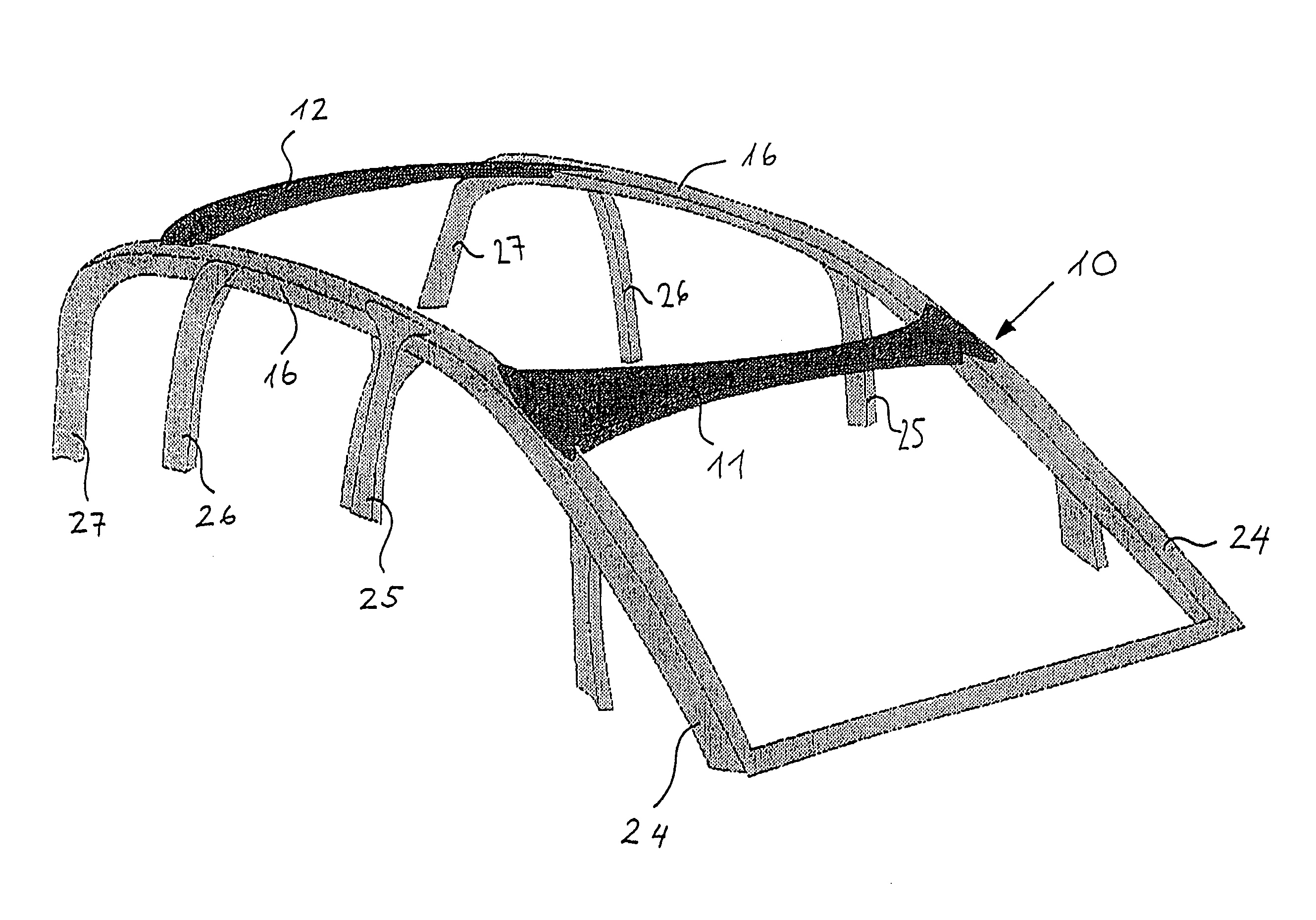
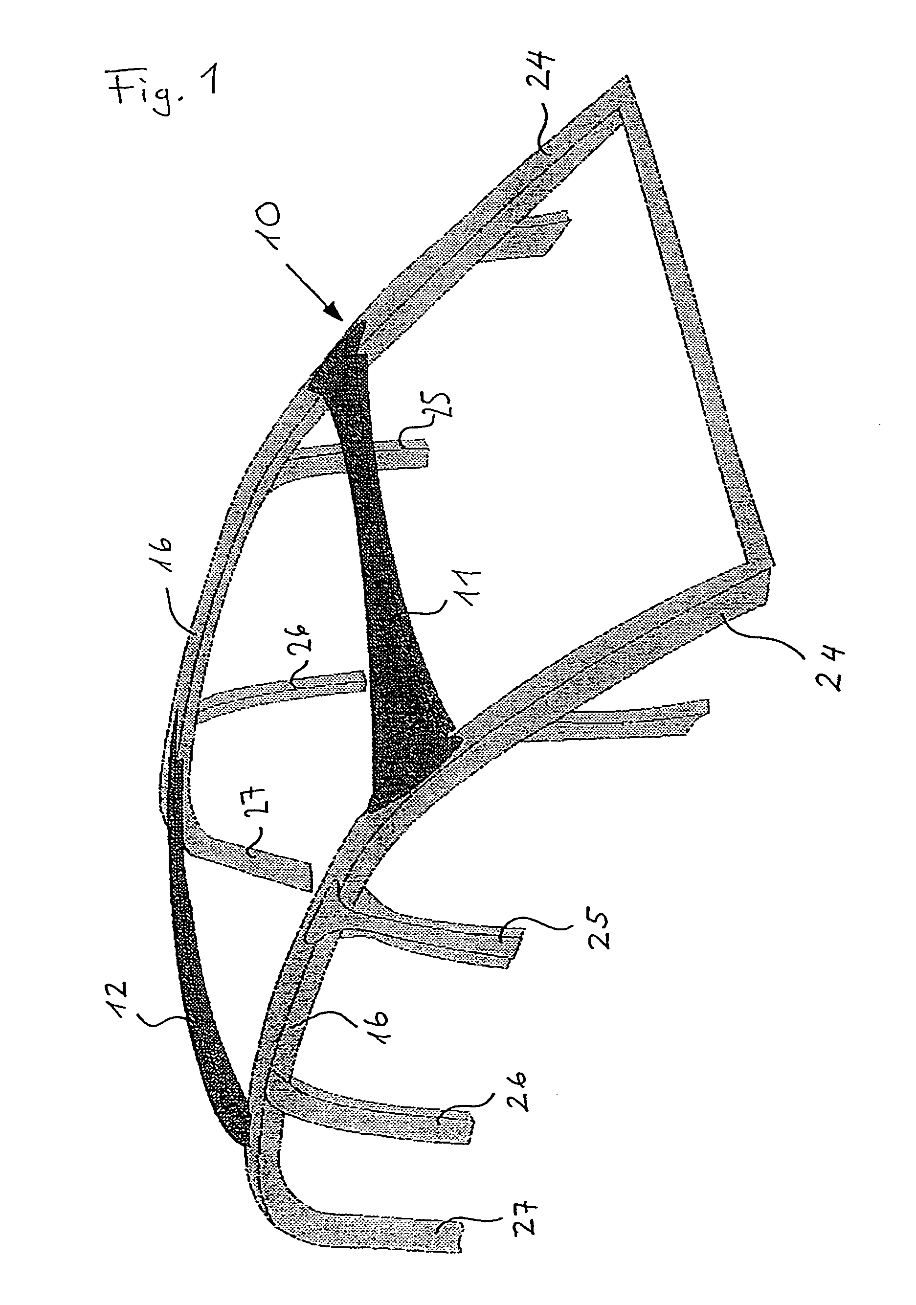
[0041]Shown in FIG. 1 is a basic structure 10 of a vehicle body which already has the side wall columns 24, 25, 26, 27, the front and rear cross frames 111 and 12 and the longitudinal frame members 16. The basic structure 10 may feature further component parts; as these are not pertinent to the object of the invention they not shown here.

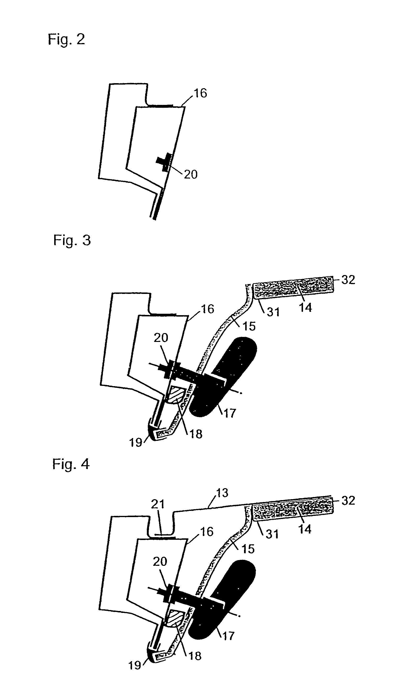
[0042]FIG. 2 shows a cross-section through a longitudinal frame member 16 which represents the upper limit of the basic structure 10. The longitudinal frame features an extrusion seal 19, and a connecting element 20 features e.g. an internal thread, a sleeve etc. When the car body is being assembled, the roof unit is fitted onto the largely prefabricated basic structure 10.

[0043]FIG. 3 shows further parts that can be built onto the basic structure 10 e.g. the ceiling 14, such as a foamed body 32 covered with a lining 31, ceiling frame 15 and airbag module 18 e.g. for side wall airbags, window airbags or head / shoulder airbags. During production of th...


PUM

PropertyMeasurementUnit
stabilityaaaaaaaaaa
structural strengthaaaaaaaaaa
transparentaaaaaaaaaa

Abstract

A roof unit having an outer skin, an inward facing ceiling having a ceiling frame, and a basic structure. The ceiling and the outer skin along with the basic structure have joining configurations that mate together at corresponding locations. The ceiling has at least one fitting from a group of fittings including fittings for a ceiling cover, interior cladding, cushioning against impact, sun shields, an interior rear view mirror, interior lighting, wiring, operating and display elements, sliding, raising, folding, lamellar and glass roofs, and their frame parts and drive elements, and roof hand grips.

Description

CROSS-REFERENCE TO RELATED APPLICATIONS[0001]This is a divisional application of U.S. patent application Ser. No. 10 / 408,424, filed Apr. 7, 2003, which is a continuation-in-part of U.S. patent application Ser. No. 09 / 719,941, filed Dec. 18, 2000, abandoned, which is a 35 U.S.C. §371 national phase of International Application No. PCT / CH99 / 00254, filed on Jun. 11, 1999. Priority is claimed on that application and on the following application:[0002]Country: Switzerland, Application No. 1309 / 98, Filed: Jun. 18, 1998.BACKGROUND OF THE INVENTION[0003]1. Field of the invention[0004]The present invention relates to a process for manufacturing a vehicle body with a roof unit containing an outer skin and an inward facing ceiling, or an outer skin and an inward facing ceiling with a ceiling frame, whereby the roof unit is in the form of a unit ready for installation and, a basic structure, and the ceiling and the outer skin along with the basic structure feature configurations for joining tha...

Claims


Application Information

Patent Timeline
Patent Type & Authority Patents(United States)
IPC IPC(8): B21D53/88B62D25/06B62D65/00B62D65/06
CPCB62D25/06B62D65/00B62D65/06Y10T29/49904Y10T29/49867Y10T29/49622
Inventor WIESCHERMANN, JOCHENDEFLORIN, DURIMULLER, WOLFGANG
Owner ALCAN TECH & MANAGEMENT LTD
Why Eureka
Try Eureka