Eureka AIR delivers breakthrough ideas for toughest innovation challenges, trusted by R&D personnel around the world.

Circuit Device And Real-Time Clock Device

a technology of circuit devices and real-time clocks, applied in the direction of generating/distributing signals, digital storage, instruments, etc., can solve the problem that the power-on reset circuit may not be operated appropriately

Pending Publication Date: 2022-02-03
SEIKO EPSON CORP
View PDF18 Cites 0 Cited by
  • Summary
  • Abstract
  • Description
  • Claims
  • Application Information

AI Technical Summary

Benefits of technology

This patent is about a circuit device that can select between two power supply voltages and output a different voltage based on the selected power supply. The circuit device includes a power supply circuit, a predetermined circuit, and two power-on reset circuits. These circuits work together to ensure that the predetermined circuit is reset to a default level when both power-on reset signals are at a reset release level. The circuit device can be used in a real-time clock device that includes a regulator and an oscillation circuit. The technical effect of this patent is to provide an improved circuit device that allows for efficient and accurate selection and output of power supply voltages, as well as ensuring the proper resetting of the predetermined circuit.

Problems solved by technology

When the circuit device described in JP-A-2014-017965 is operated with low power consumption, for example, the voltage of the main power supply is set low, and the power-on reset circuit may not be operated appropriately.

Method used


Image

  • Circuit Device And Real-Time Clock Device
  • Circuit Device And Real-Time Clock Device
  • Circuit Device And Real-Time Clock Device

Examples


Embodiment Construction

[0019]Hereinafter, preferred embodiments of the present disclosure will be described in detail. It should be noted that the present embodiment described below does not unreasonably limit the contents described in the appended claims, and all the configurations described in the present embodiment are not necessarily essential constituent elements.

1. Basic Configuration

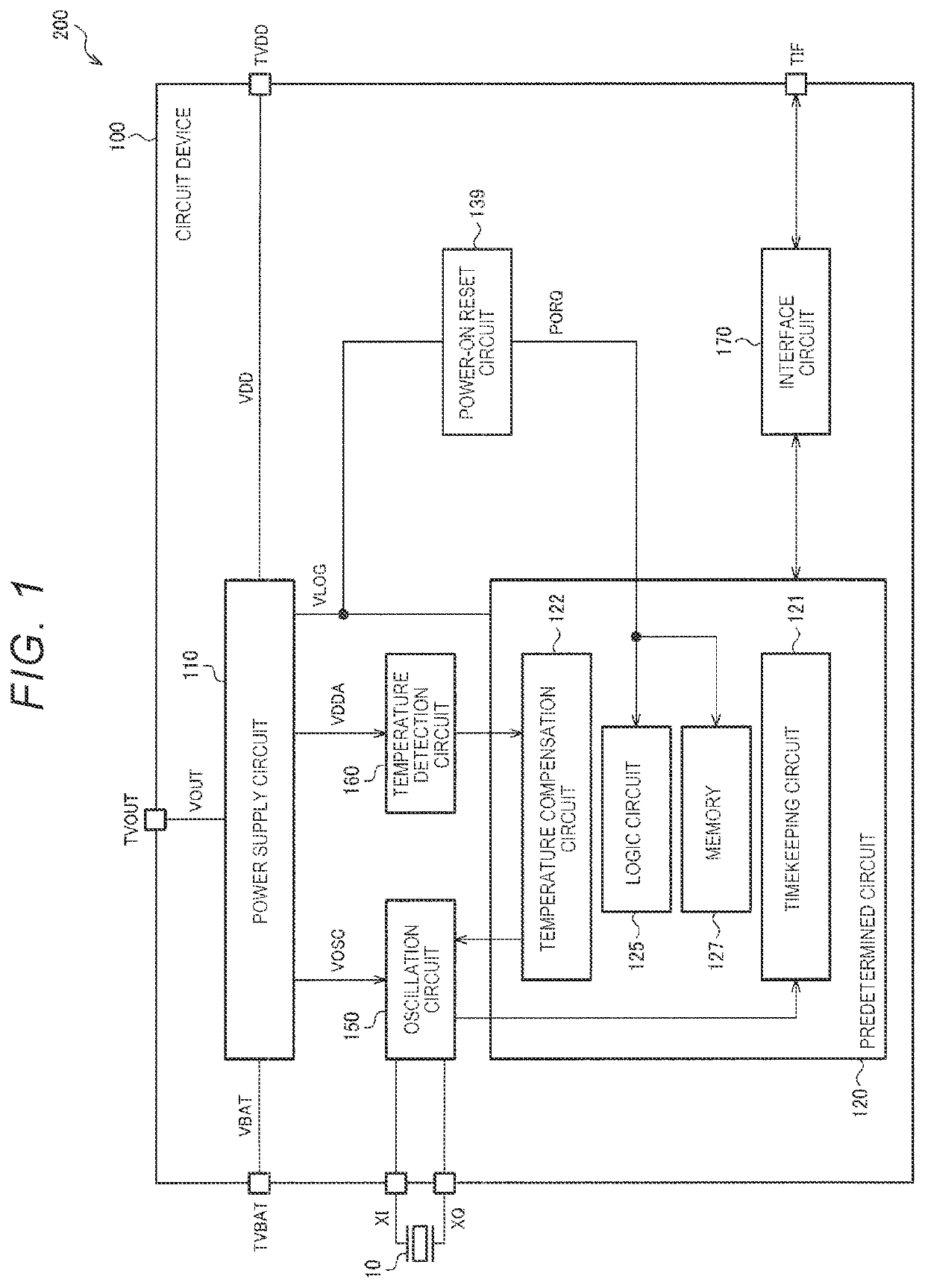
[0020]FIG. 1 is a diagram illustrating a comparative example in which the method of JP-A-2014-017965 is applied to a circuit device 100 of the present embodiment as a basic configuration. The circuit device 100 includes a first power supply line to which a first power supply voltage VDD is supplied, a second power supply line to which a second power supply voltage VBAT is supplied, a third power supply line, a power supply circuit 110, and a predetermined circuit 120. The third power supply line is a power supply line to which a third power supply voltage VLOG is supplied by the power supply circuit 110. The same applie...


PUM


Abstract

A circuit device includes a first power supply line to which a first power supply voltage is supplied, a second power supply line to which a second power supply voltage is supplied, a third power supply line, a power supply circuit, a predetermined circuit, a first power-on reset circuit, a second power-on reset circuit, and a reset control circuit. When a first power-on reset signal and a second power-on reset signal become a reset release level, the reset control circuit sets a third power-on reset signal output to at least a part of the predetermined circuit to a reset release level.

Description

[0001]The present application is based on, and claims priority from JP Application Serial Number 2020-128473, filed Jul. 29, 2020, the disclosure of which is hereby incorporated by reference herein in its entirety.BACKGROUND1. Technical Field[0002]The present disclosure relates to a circuit device, a real-time clock device, and the like.2. Related Art[0003]A power-on reset circuit that initializes the internal state of a circuit device by generating an internal reset signal when power is turned on or a power supply voltage drops in the circuit device is known.[0004]JP-A-2014-017965 discloses that a circuit device including a switch circuit for switching between a main power supply and a backup power supply includes a power-on reset circuit that can be coupled to either the main power supply or the backup power supply.[0005]Since it is desirable to hold each circuit in the circuit device in reset until a constant voltage is supplied, a minimum drive voltage is set. When the circuit d...

Claims


Application Information

Patent Timeline
IPC IPC(8): G06F1/14G11C7/22G11C7/04
CPCG06F1/14G11C7/04G11C7/222H03L1/00H03L5/00H02J9/06G11C5/14G11C5/148G11C7/20G11C5/143G06F1/24
Inventor MATSUZAKI, SHO
Owner SEIKO EPSON CORP
Why Eureka
Eureka Blog
Learn More