Supercharge Your Innovation With Domain-Expert AI Agents!

Bearing housing and a method of removing impurities from a bearing housing

a technology of bearing housing and bearing housing, which is applied in the direction of settling tank feed/discharge, bearing unit rigid support, separation process, etc., can solve the problems of impurities loosening from the interior surface of the bearing housing, oil used for lubricating the bearings is contaminated in a few different ways, and the impurities can also get into the bearing housing from outside, so as to improve the settling of impurities

Pending Publication Date: 2022-02-10
SULZER MANAGEMENT AG
View PDF4 Cites 0 Cited by
  • Summary
  • Abstract
  • Description
  • Claims
  • Application Information

AI Technical Summary

Benefits of technology

The invention provides a bearing housing that can remove impurities without replacing all the oil inside it. The impurities are collected in a separate chamber where the oil flow is smoother, which makes it easier for the impurities to settle. The technical effect of this invention is to improve the efficiency and lifespan of bearing housings by removing impurities without replacing all the oil.

Problems solved by technology

Normally, the oil used for lubricating the bearings is contaminated in a few different ways.
Impurities can also loosen from the interior surface of the bearing housing, and impurities can also get into the bearing housing from outside thereof, due to, for instance, a seal failure.
Usually the impurities sink to the bottom of the housing, but it is not uncommon that the circulation of oil and the turbulence prevailing in the bearing housing keep the impurities moving, at least the smallest or the lightest ones such that they get into contact with the bearing surfaces and speed up the wear thereof.
Such paste-like material cannot normally be removed from the bearing housing as the removal may, at its worst, require mechanical working on the material until it is loosened from the surface of the housing.

Method used


Image

  • Bearing housing and a method of removing impurities from a bearing housing
  • Bearing housing and a method of removing impurities from a bearing housing
  • Bearing housing and a method of removing impurities from a bearing housing

Examples


Embodiment Construction

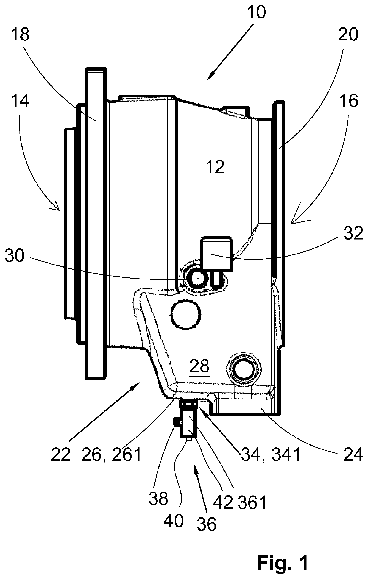
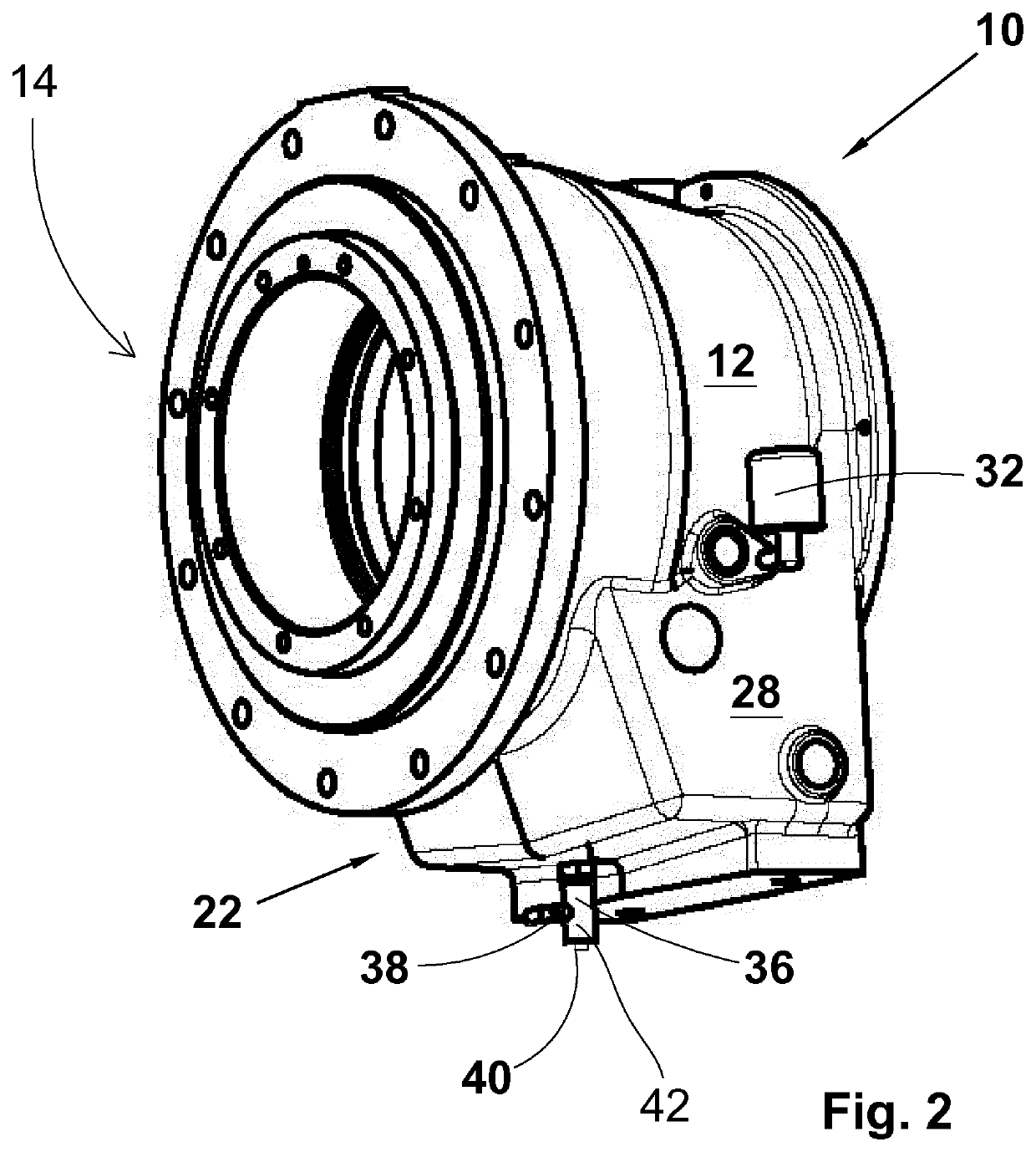
[0030]FIG. 1 depicts a side view of a bearing housing 10 and FIG. 2 depicts an isometric view of the bearing housing 10 in accordance with an embodiment of the present invention. The bearing housing 10 normally has a tubular shape, i.e. it has a hollow shell 12 with circular openings 14 and 16 at its both ends. The cross section of the shell 12 normally has a cylindrical, rectangular or square shape, though, naturally, the cross section of the shell can have any imaginable shape that fits with the use of the shell. The openings 14 and 16 are coaxial so that a shaft can run through the bearing housing 10. The openings 14 and 16 are configured to provide attachment of bearings for the shaft. Normally, there is one bearing or a set of bearings installed at each opening, and the openings can have the same or a different diameter. One or both openings 14 and 16 can be surrounded with flange / s 18 and 20, respectively, so that the bearing housing 10 can be fastened to neighbouring componen...


PUM

PropertyMeasurementUnit
distanceaaaaaaaaaa
timeaaaaaaaaaa
periods of timeaaaaaaaaaa

Abstract

A bearing housing includes a hollow shell with opposite ends having coaxial openings for at least one bearing element at each end thereof. The shell between the openings has, when assembled in position for use, a bottom with a bottom surface, the bottom having an oil outlet and the bottom surface having an oil outlet opening. The cavity for impurities is arranged below the bottom surface of the shell, and the cavity is arranged in flow communication with the oil outlet and the oil outlet opening.

Description

CROSS-REFERENCE TO RELATED APPLICATIONS[0001]This application is a U.S. National Stage application of International Application No. PCT / EP2019 / 082731, filed Nov. 27, 2019, which claims priority to European Patent Application No. 18210244.2, filed Dec. 4, 2018, the contents of which are hereby incorporated herein by reference.BACKGROUNDField of the Invention[0002]The present invention relates to a bearing housing and a method of removing impurities from the bearing housing. More generally, the present invention relates to bearing housings used in connection with various machines, like for instance centrifugal pumps, radial pumps, agitators, mixers, etc.Background Information[0003]Normally, the oil used for lubricating the bearings is contaminated in a few different ways. Impurities found in the lubricating oil can be originating from the wear of the bearing balls, rollers, inner and outer races or cages. Impurities can also loosen from the interior surface of the bearing housing, and...

Claims


Application Information

Patent Timeline
Patent Type & Authority Applications(United States)
IPC IPC(8): F16C33/66B01D21/24F16C35/04F16N31/00F16N39/00
CPCF16C33/6685B01D21/2483F16C35/042F16N2210/14F16N39/00F16C2320/16F16C2360/44F16N31/00F16N2031/008B01D17/0214B01D21/245
Inventor NYMAN, SEPPORIPATTILA, JANNE
Owner SULZER MANAGEMENT AG
Features
  • R&D
  • Intellectual Property
  • Life Sciences
  • Materials
  • Tech Scout
  • Unparalleled Data Quality
  • Higher Quality Content
  • 60% Fewer Hallucinations
Learn More