Exhaust gas purification apparatus

a technology of exhaust gas and purification apparatus, which is applied in mechanical apparatus, machines/engines, separation processes, etc., can solve the problems of increased exhaust emissions, reduced purification capacity of urea-scr apparatus, and difficulty in supplying ammonia gas and exhaust gas. to the level of sufficient,

Inactive Publication Date: 2008-01-31
DENSO CORP
View PDF9 Cites 37 Cited by
  • Summary
  • Abstract
  • Description
  • Claims
  • Application Information

AI Technical Summary

Benefits of technology

[0035]The first injection orifice may be located so as to be

Problems solved by technology

If the hydrolysis of the urea solution performed upstream of the catalyst 51 is insufficient, and accordingly the amount of the ammonia is not sufficient to purify (reduce) the NOx contained in the exhaust gas, the purification capacity of the urea-SCR apparatus is lowered, which causes exhaust emissions to increase.
This make it difficult for the ammonia gas and the exhaust gas to suff

Method used


Image

  • Exhaust gas purification apparatus
  • Exhaust gas purification apparatus
  • Exhaust gas purification apparatus

Examples


Embodiment Construction

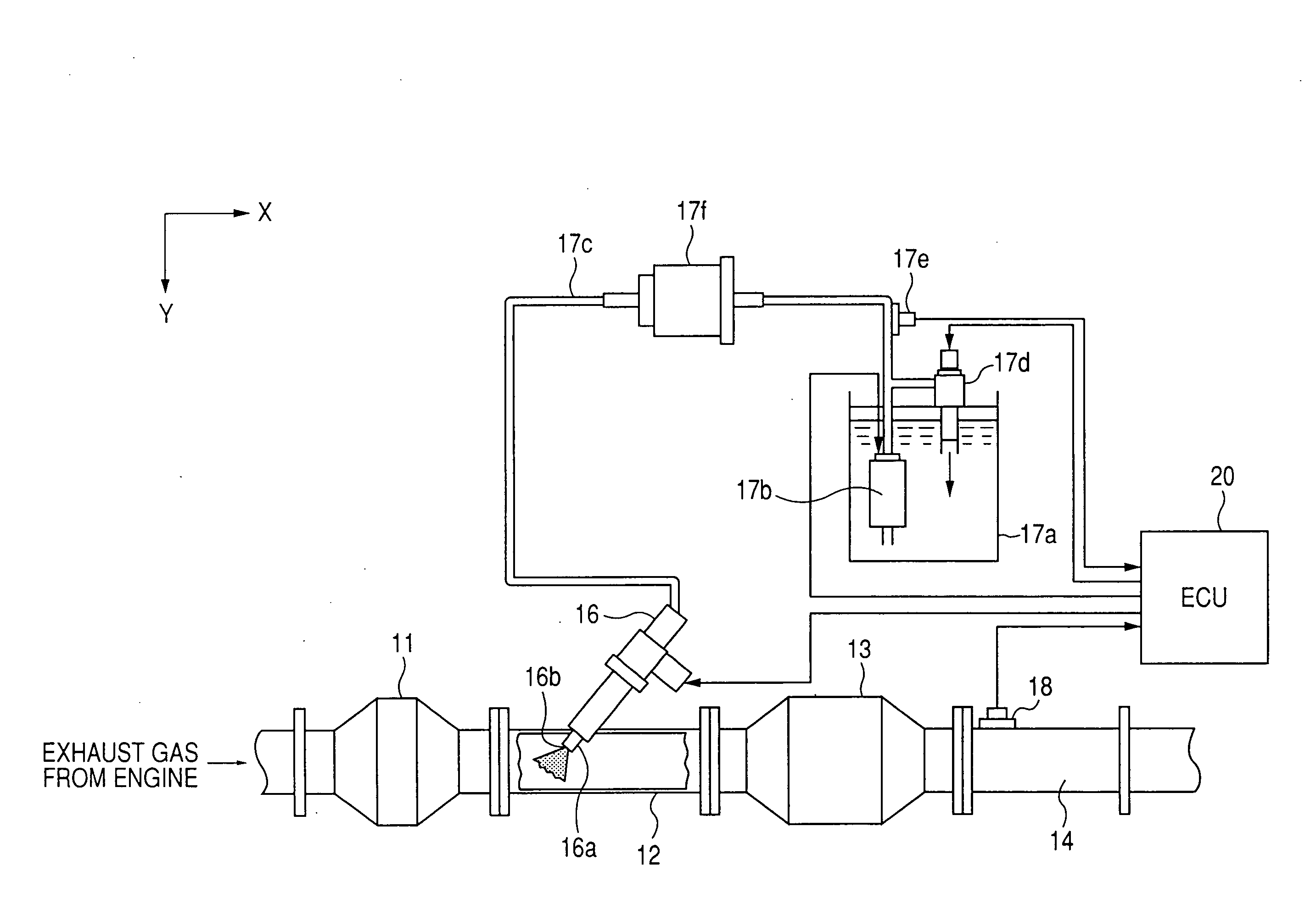
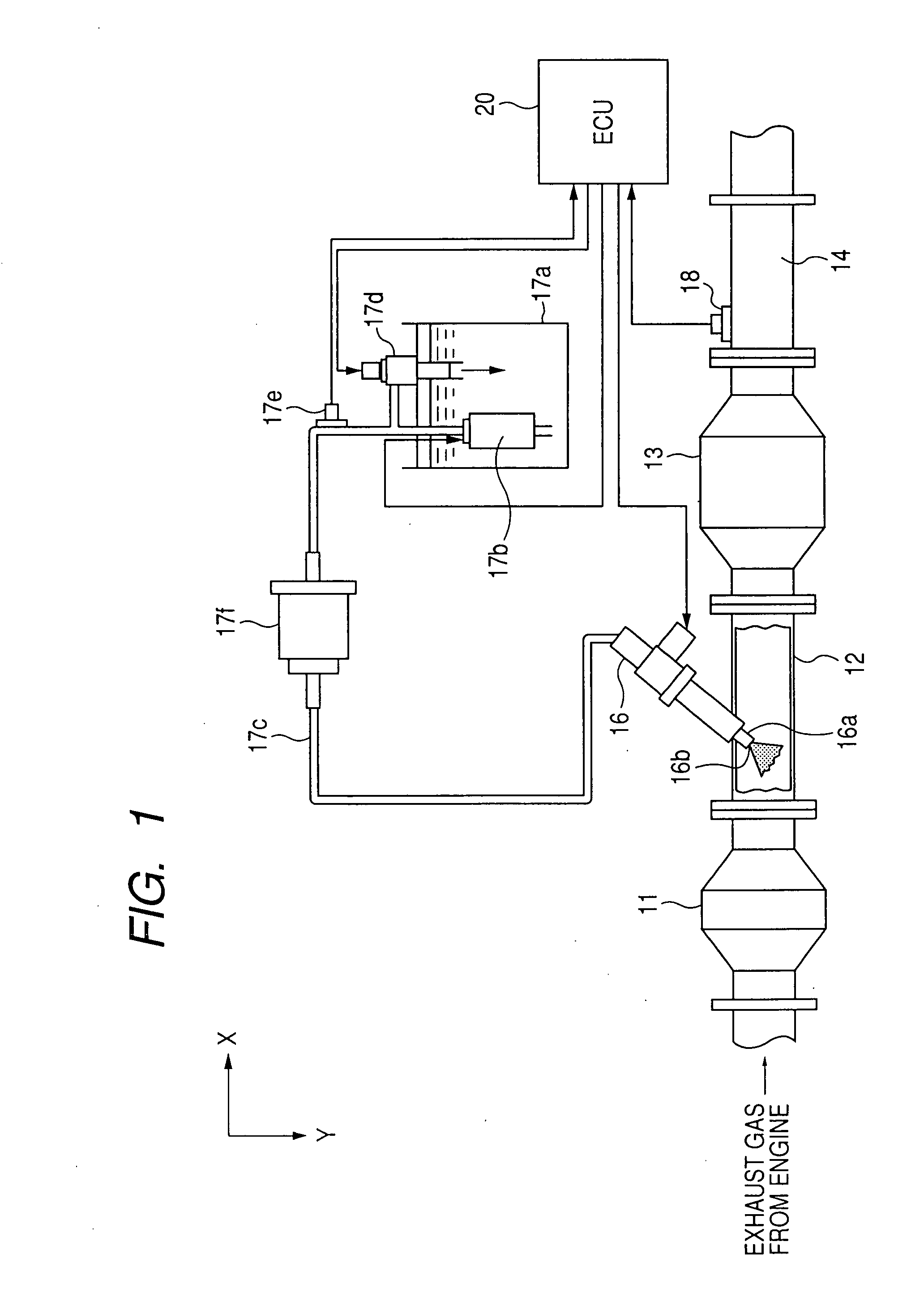
[0063]FIG. 1 is a diagram showing a structure of a urea-SCR system as an exhaust gas purification apparatus according to an embodiment of the invention. In FIG. 1, the arrow X represents a horizontal direction (X-direction), and the arrow Y represents a vertical direction or the gravitational direction (Y-direction).

[0064]This system, which is for purifying exhaust gas discharged from a diesel engine mounted on a vehicle (not shown), includes various actuators, sensors, ECU (Electronic Control Unit) 20, etc.

[0065]More specifically, this system includes a DPF (Diesel Particulate Filter) 11, an exhaust pipe 12, a catalyst 13, an exhaust pipe 14 disposed in this order from the exhaust upstream side, and is configured to inject a urea solution into exhaust gas flowing through the exhaust pipe 12 between the DPF 11 and the catalyst 13 from an additive injection valve 16 disposed midway of the exhaust pipe 12. In this system, the catalyst 13 disposed downstream of the additive injection v...


PUM

PropertyMeasurementUnit
Flow rateaaaaaaaaaa
Gravityaaaaaaaaaa

Abstract

The exhaust gas purification apparatus includes an additive injection valve for injecting an additive from an injection orifice thereof into an exhaust gas passage through which an exhaust gas flows, and a catalyst disposed downstream of the additive injection valve for promoting an exhaust purification reaction using the additive to purify the exhaust gas. The exhaust gas purification apparatus is configured to inject-supplies, from the additive injection valve, the additive to the exhaust gas by the additive injection valve at upstream of the catalyst, and supply the catalyst with the injected additive together with the exhaust gas utilizing an exhaust flow of the exhaust gas so that the exhaust purification reaction is performed on the catalyst. The additive injection valve is mounted such that the additive is injected from the injection orifice toward an exhaust upstream side with respect to a direction orthogonal to an exhaust gas flow direction.

Description

CROSS-REFERENCE TO RELATED APPLICATION[0001]This application is related to Japanese Patent Applications No. 2006-204071 filed on Jul. 27, 2006, and No. 2007-67348 filed on Mar. 15, 2007, the contents of which are hereby incorporated by reference.BACKGROUND OF THE INVENTION[0002]1. Field of the Invention[0003]The present invention relates to an exhaust gas purification apparatus for purifying exhaust gas by performing an exhaust gas purification reaction on a catalyst by use of a designated additive, as typified by the urea-SCR (selective reduction) system, and more specifically relates to an exhaust gas purification apparatus that promotes, through a catalyst, an exhaust gas purification reaction by use of an additive such as a urea solution injected from an additive injection valve, to thereby purify exhaust gas.[0004]2. Description of Related Art[0005]Various urea-SCR systems are under development with expectation of purifying NOx contained in exhaust gas at high purification rate...

Claims


Application Information

Patent Timeline
IPC IPC(8): F01N3/20
CPCB01D53/90B01D53/9431B01D2251/2067F01N3/2066Y02T10/24F01N2610/11F01N2610/1426F01N2610/1453F01N2610/02Y02T10/12
Inventor ICHIKAWA, ATARU
Owner DENSO CORP
Why Eureka
Try Eureka