Power Converter and Power Conversion System

Pending Publication Date: 2022-02-10
MITSUBISHI ELECTRIC CORP
View PDF0 Cites 0 Cited by
  • Summary
  • Abstract
  • Description
  • Claims
  • Application Information

AI Technical Summary

Benefits of technology

The present patent provides a way to efficiently discharge the capacitors of each submodule by making use of an existing facility. This results in improved performance of the overall system.

Problems solved by technology

It thus takes a long time before a person can approach the power converter.

Method used


Image

  • Power Converter and Power Conversion System
  • Power Converter and Power Conversion System
  • Power Converter and Power Conversion System

Examples


embodiment 1

[0022]

[0023]Overall Configuration

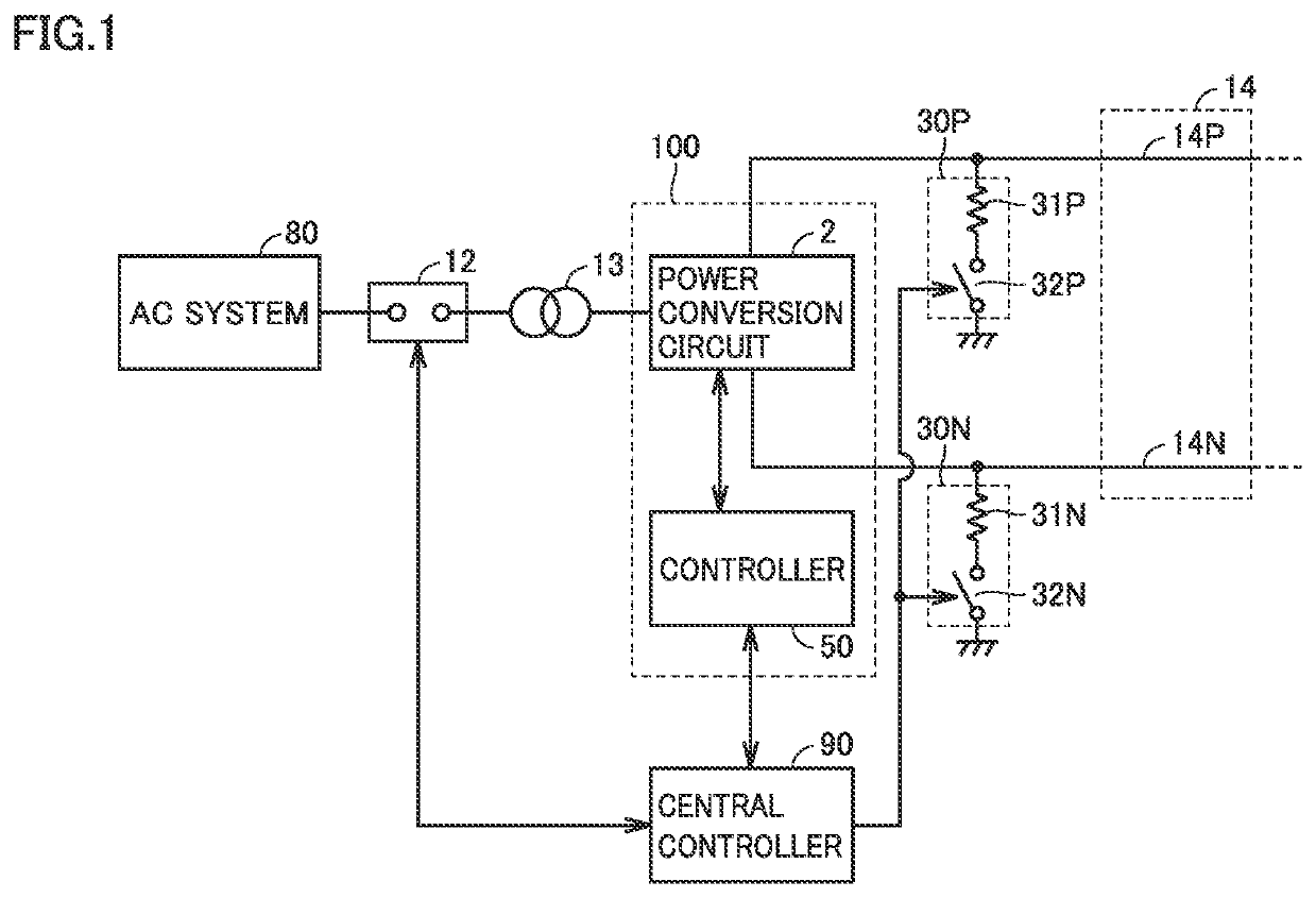
[0024]FIG. 1 shows an example schematic configuration of a power conversion system according to Embodiment 1. Referring to FIG. 1, the power conversion system is a system for controlling electric power of a DC power transmission system of single pole configuration. Electric power is transmitted and received between an AC system 80 and another AC system through a positive-side DC power transmission line 14P and a negative-side DC power transmission line 14N of a DC line 14. DC line 14 is typically a cable having a capacitance.

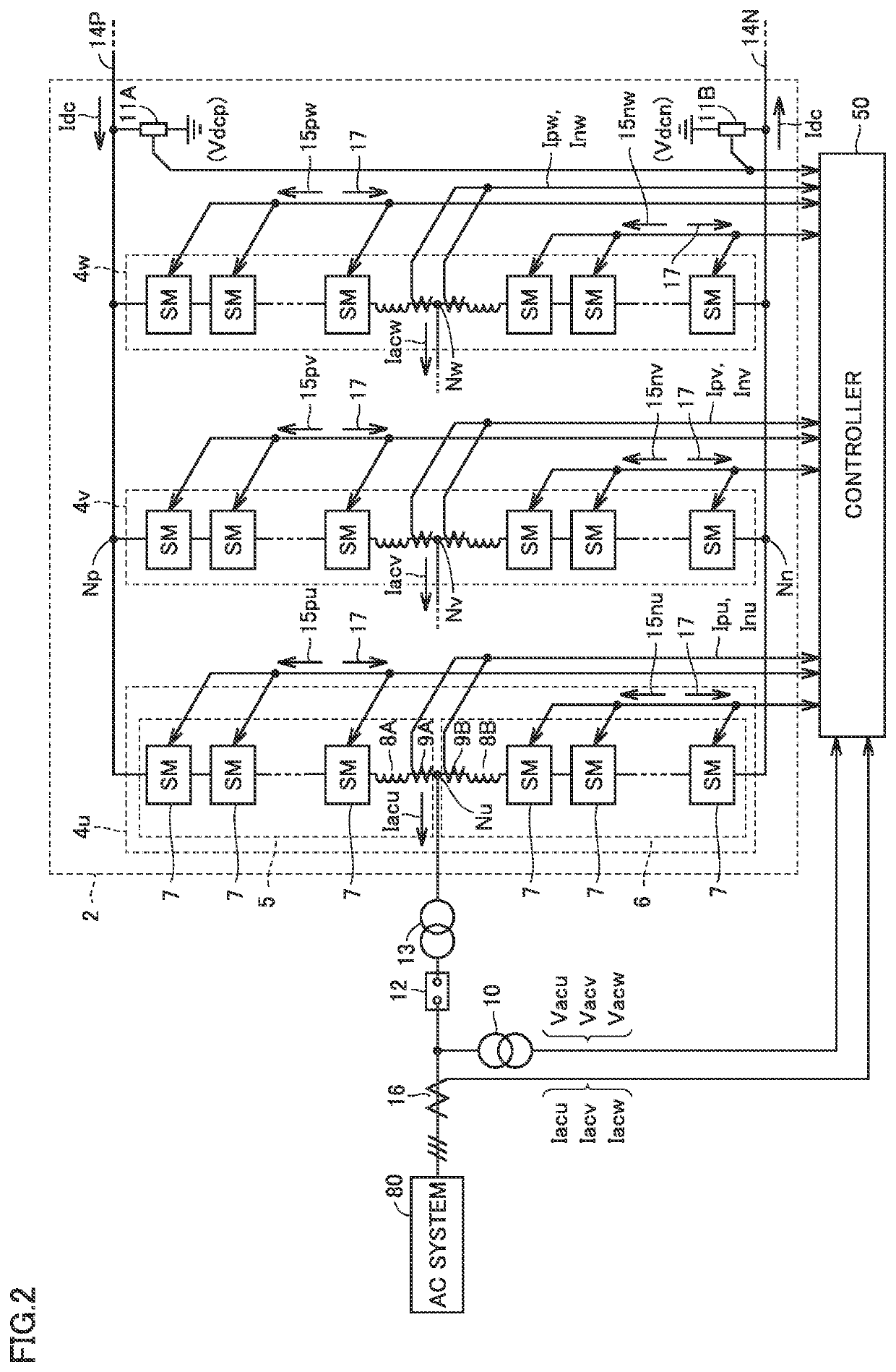
[0025]Power converter 100 performs power conversion between DC line 14 and AC system 80. Specifically, power converter 100 includes a power conversion circuit 2 and a controller 50. Power conversion circuit 2 is connected to DC power transmission lines 14P, 14N. Controller 50 controls an operation of power conversion circuit 2. Specific processes performed by controller 50 will be described below. Power conversion circuit 2 is co...

embodiment 2

[0123]Embodiment 1 has described a configuration in which electric charges of capacitor 24 are self-discharged after controller 50 is unable to communicate with submodule 7. Embodiment 2 will describe a configuration in which electric charges of capacitor 24 are discharged via discharge circuit 30 using a thyristor even when controller 50 is unable to communicate with each submodule 7.

[0124]Embodiment 2 is different from Embodiment 1 in that a thyristor is provided in a submodule. The overall configuration of Embodiment 2, the configuration of power conversion circuit 2, and the hardware configuration of controller 50 are similar to the configurations of Embodiment 1.

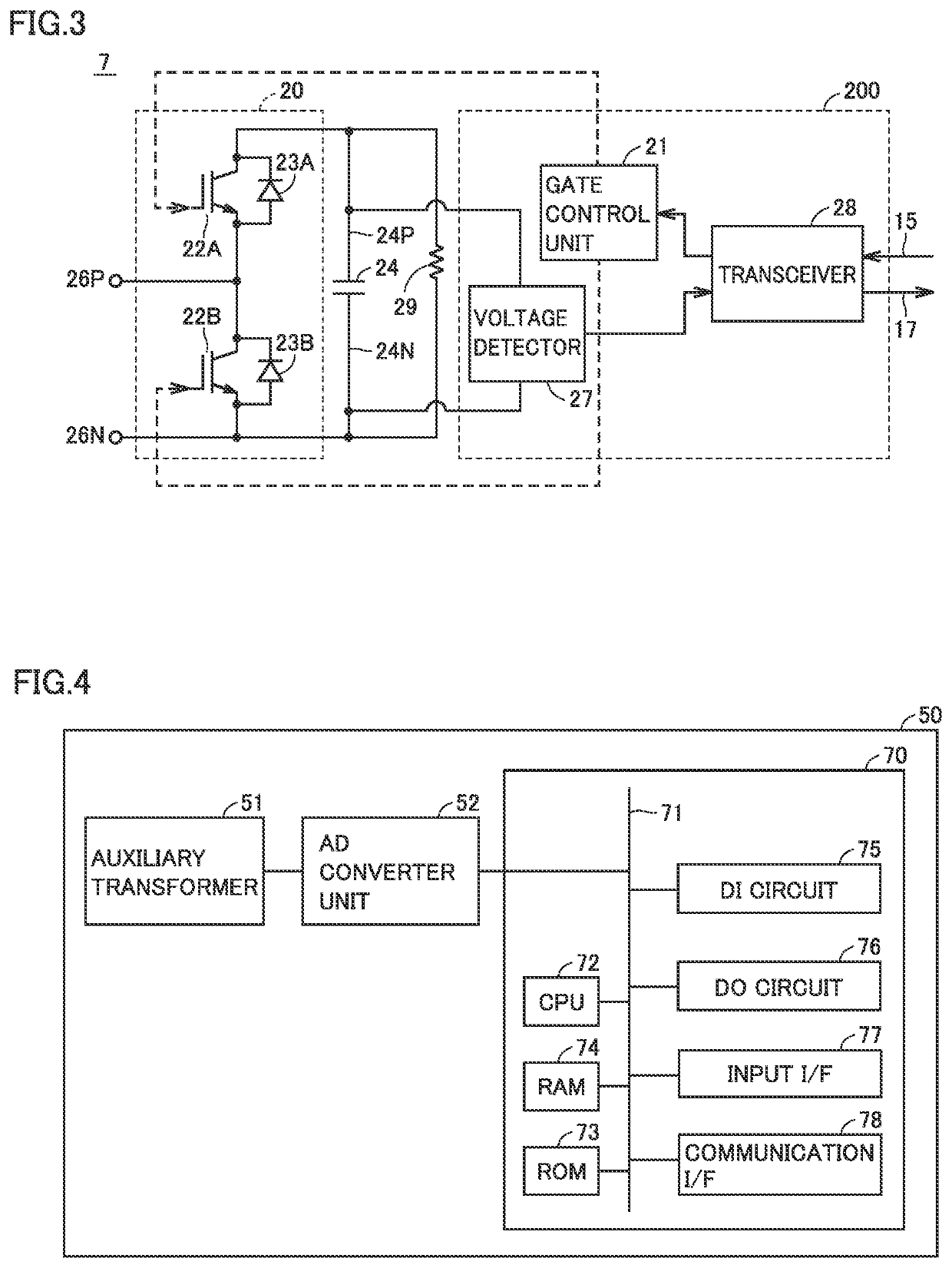
[0125]FIG. 8 is a circuit diagram showing an example submodule according to Embodiment 2. Referring to FIG. 8, a submodule 7A is obtained by replacing switching circuit 20 of submodule 7 shown in FIG. 3 with a switching circuit 20A.

[0126]Switching circuit 20A is obtained by connecting thyristor 41 in parallel with switc...


PUM


Abstract

A power converter that performs power conversion between a DC line and an AC system includes a power conversion circuit including a plurality of submodules connected in series with each other, and a controller to control each of the plurality of submodules. Each submodule includes a switching circuit and a capacitor connected in parallel with the switching circuit. When a circuit breaker provided between the AC system and the power conversion circuit is opened, the controller drives the switching circuit of at least one submodule of the plurality of submodules such that the capacitor of the at least one submodule is discharged via a discharge circuit connected to the DC line.

Description

TECHNICAL FIELD[0001]The present disclosure relates to a power converter and a power conversion system that perform power conversion between alternating current (AC) and direct current (DC).BACKGROUND ART[0002]As a power converter for electrical power system such as a high voltage direct current (HVDC) or a static synchronous compensator (STATCOM), a modular multilevel converter (MMC) with an internal high-capacity capacitor is known. The MMC converter includes an upper arm connected to a high-potential-side DC terminal and a lower arm connected to a lower-potential-side DC terminal for each phase of AC. Each arm is composed of multiple cascaded submodules. “Submodule” is also referred to as a “converter cell”.[0003]When an operation of the power converter is stopped in maintenance service or the like, electric charges stored in the capacitor of each submodule are gradually discharged. An electronic circuit of the above-mentioned power converter is, however, designed to have the sma...

Claims


Application Information

Patent Timeline
IPC IPC(8): H02M7/483H02M1/36H02M1/32H02M7/49H02J3/36
CPCH02M7/4835H02M1/36H02J3/36H02M7/49H02M1/32Y02E60/60H02M1/322
Inventor TAKAHASHI, TATSUYAHAYASHI, SHIGEO
Owner MITSUBISHI ELECTRIC CORP
Why Eureka
Try Eureka