Guided wave Radar level gauge with explosion proof housing and floating barrier

a radar level gauge and floating barrier technology, applied in the field of radar level gauges, can solve the problems of deteriorating energy budget, explosion proof, and insufficient explosion proof approach, and achieve the effect of reducing the number of signals passing through the barrier and larger voltage drop across the barrier

Pending Publication Date: 2022-02-17
ROSEMOUNT TANK RADAR
View PDF0 Cites 1 Cited by
  • Summary
  • Abstract
  • Description
  • Claims
  • Application Information

AI Technical Summary

Benefits of technology

[0026]The number of signals passing through the barrier may be reduced by arranging the frequency generator (e.g. a dual oscillator timing circuit, a delay lock loop, DLL, or a phase locked loop, PLL) downstream the barrier. In that case, the clock signals are generated on the microwave unit side, and do not need to pass the barrier. A drawback with this approach is that the frequency generator requires more power, thus causing a larger voltage drop across the barrier. Such a voltage drop increases the minimum voltage required to operate the RLG, sometimes referred to as “lift-off voltage”. This voltage is an important design parameter in many applications where power is a limited resource (e.g. RLG powered by a two-wire control loop or internal battery).

Problems solved by technology

Inside the tank, explosion proof is not a sufficient approach.
For guided wave radar (GWR), however, where the probe extends into the tank interior, explosion proof is not sufficient, and GWR level gauges are therefore typically designed to be intrinsically safe.
Unfortunately, when a radar level gauge with such an IS barrier is placed on a 4-20 mA control loop, where the current may be as high as 20 mA, the resistors in the barrier will cause a voltage drop which deteriorates the energy budget.
However, due to possible potential differences between the power supply ground and the chassis ground, design of such IS-barriers is challenging, and tends to result in a complex and expensive design with a large number of components.
The only energy output to the probe will be generated by the microwave unit, and thus inherently limited to IS standards.
However, in theory the potential of such a floating barrier may be different than the potential of the tank, thereby allowing DC components between the probe connection and the probe, thus making it incompatible with some IS requirements.

Method used


Image

  • Guided wave Radar level gauge with explosion proof housing and floating barrier
  • Guided wave Radar level gauge with explosion proof housing and floating barrier
  • Guided wave Radar level gauge with explosion proof housing and floating barrier

Examples


Embodiment Construction

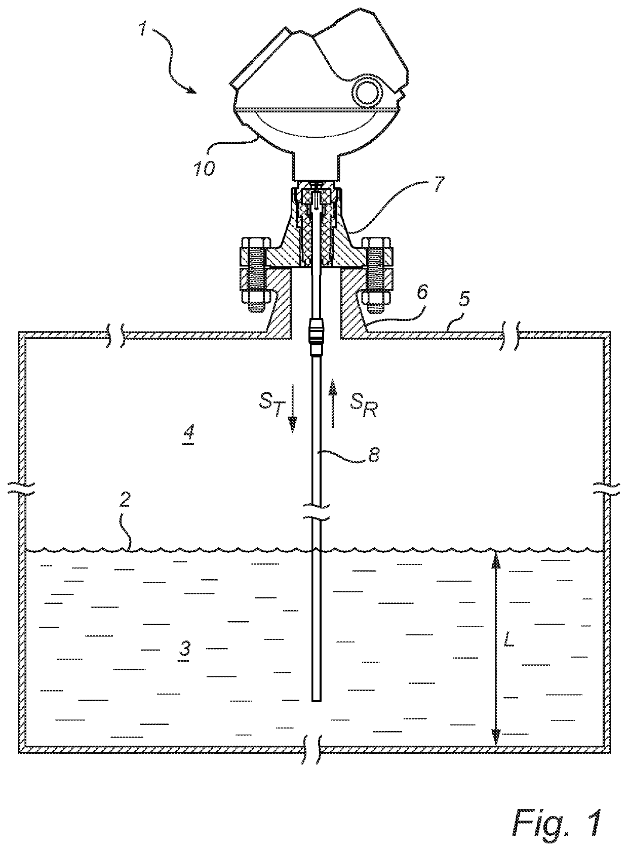
[0032]An embodiment of the present invention will now be disclosed with reference to a pulsed radar level gauge. In the context of radar level gauging, a pulsed system determines the distance to the surface of the product contained in the tank based on the difference in time (time-of-flight) between transmission of a pulse and reception of its reflection at the surface of the product. Most pulsed radar level gauge systems employ Time Domain Reflectometry (TDR), which provides a time expansion of the (extremely short) time-of-flight. Such TDR radar level gauge systems generate a transmit pulse train having a first pulse repetition frequency Tx, and a reference pulse train having a second pulse repetition frequency Rx that differs from the transmitted pulse repetition frequency by a known frequency difference Of. This frequency difference Af is typically in the range of Hz or tens of Hz.

[0033]The transmit pulse train is emitted by a propagating device towards the surface of a product ...


PUM


Abstract

A guided wave radar level gauge comprising a housing providing explosion proof protection and having an intrinsically safe output, a transmission line probe connected to the IS output. The housing encloses radar level gauge circuitry which is incompatible with intrinsic safety requirements, a microwave unit connected to the IS output, an electrical barrier connected between the RLG circuitry and the microwave unit, the electrical barrier having a barrier ground potential which is independent from the grounded housing wall, and a set of blocking capacitors connected between the microwave unit and the IS output.

Description

FIELD OF THE INVENTION[0001]The present invention relates to a radar level gauge having an explosion proof (e.g. Ex-d) compartment with an intrinsically safe (e.g. Ex-ia) connection. Such an explosion proof compartment with an IS connection is particularly desired in a guided wave radar (GWR) level gauge.BACKGROUND OF THE INVENTION[0002]Radar level gauge (RLG) systems are in wide use for determining the filling level of a product contained in a tank. Radar level gauging is generally performed either by means of non-contact measurement, whereby electromagnetic signals are radiated towards the product contained in the tank, or by means of contact measurement, often referred to as guided wave radar (GWR), whereby electromagnetic signals are guided towards and into the product by a probe acting as a waveguide. The probe is generally arranged to extend vertically from the top towards the bottom of the tank. The probe may also be arranged in a measurement tube, a so-called chamber, which ...

Claims


Application Information

Patent Timeline
Patent Type & Authority Applications(United States)
IPC IPC(8): G01F23/284H02H9/00
CPCG01F23/284H02H9/008G01S13/88
Inventor NILSSON, LEIFNYBERG, HÅKANERIKSSON, MIKAEL
Owner ROSEMOUNT TANK RADAR
Why Eureka
Try Eureka