Outer panel-mediated cooling system

a technology of cooling system and outer panel, which is applied in the direction of energy-efficient board measures, air-treatment apparatus arrangements, transportation and packaging, etc., can solve the problems of increasing air resistance, and achieve the effect of increasing the variety of choices

Active Publication Date: 2022-03-03
KAWASAKI HEAVY IND LTD
View PDF3 Cites 0 Cited by
  • Summary
  • Abstract
  • Description
  • Claims
  • Application Information

AI Technical Summary

Benefits of technology

[0012]The present invention can provide an outer panel-mediated cooling system of a transportation machine that uses a cooled gas resulting from heat exchange with an external fluid via an outer panel, the system being adapted to increase the variety of choices for the cooling target.

Problems solved by technology

The use of such a heat sink has posed problems such as increased air resistance due to discontinuity of the aircraft body surface and entry of foreign matter into the air scoop.

Method used


Image

  • Outer panel-mediated cooling system
  • Outer panel-mediated cooling system
  • Outer panel-mediated cooling system

Examples


Embodiment Construction

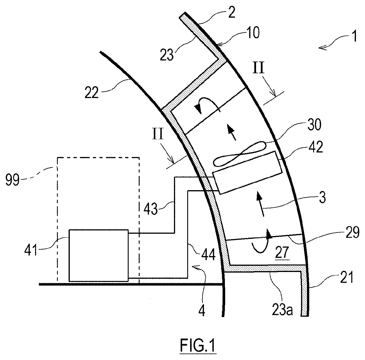
[0021]Hereinafter, an exemplary embodiment of the present invention will be described with reference to the drawings. An outer panel-mediated cooling system 1 according to the exemplary embodiment is applicable to transportation machines such as watercrafts (including submersibles), railcars, automobiles, and aircrafts, and used to cool a cooling target 99 located in a transportation machine. The following describes an example where the outer panel-mediated cooling system 1 is applied to an aircraft 10 which is an example of the transportation machine.

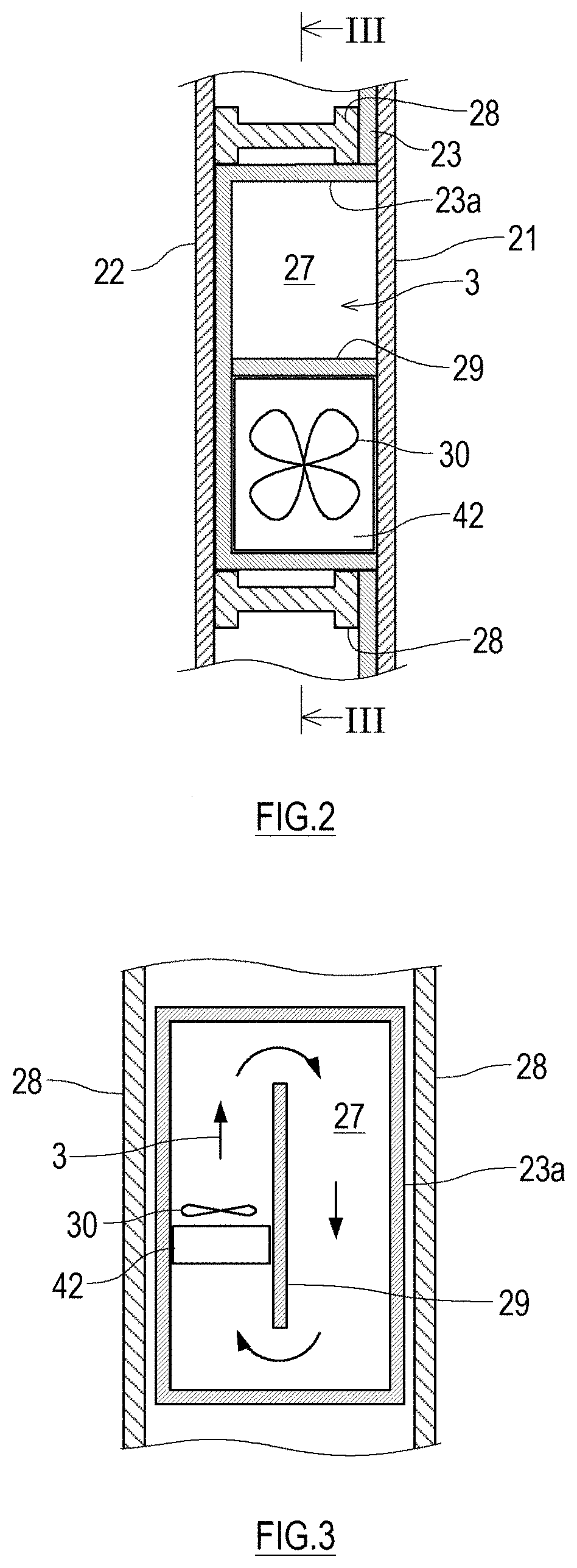
[0022]FIG. 1 illustrates a schematic configuration of the outer panel-mediated cooling system 1 according to the exemplary embodiment of the present invention, FIG. 2 is a cross-sectional view taken along the arrow II-II of FIG. 1, and FIG. 3 is a cross-sectional view taken along the arrow III-III of FIG. 2. Shown in FIG. 1 is a cross-section of a part of the fuselage of the aircraft 10 which is an example of the transportation machine...


PUM


Abstract

An outer panel-mediated cooling system includes: an outer shell including an outer panel, an inner panel located inward of the outer panel, and a heat-insulating layer located between the outer and inner panels; a cooling chamber that is located between the outer and inner panels and in which a gas releases heat outside through the outer panel and is thus cooled; a circulation loop in which a heat medium circulates, the circulation loop including a heating section located inward of the inner panel to heat the heat medium and a cooling section located in the cooling chamber to cool the heat medium; a flow path-forming structure located in the cooling chamber to form a circulation path for the gas; and a fan located in the cooling chamber to exert a drive force on the gas to allow the gas to circulate in the circulation path.

Description

TECHNICAL FIELD[0001]The present invention relates to an outer panel-mediated cooling system using a cooled gas resulting from heat exchange with an external fluid via an outer panel.BACKGROUND ART[0002]In recent years, transportation machines have been increasingly electrified, and electronic devices have become more and more sophisticated and miniaturized. This has led to a growing demand for thermal management in transportation machines such as watercrafts, railcars, automobiles, and aircrafts which are equipped with a large number of the sophisticated, miniaturized devices. Aircrafts, which are an example of the transportation machines, have traditionally incorporated a heat sink to cool the electronic devices. The heat sink makes use of high-altitude cool air taken in through an air scoop located on the aircraft body surface. The use of such a heat sink has posed problems such as increased air resistance due to discontinuity of the aircraft body surface and entry of foreign mat...

Claims


Application Information

Patent Timeline
Patent Type & Authority Applications(United States)
IPC IPC(8): B64D13/00
CPCB64D13/006B64D13/08B64D2013/0614Y02T50/50B64D2013/0674
Inventor HARUKI, YUSAKAGAWA, KEIJIHAKAMADA, KAZUHIDEMITANI, RYOSUKE
Owner KAWASAKI HEAVY IND LTD
Why Eureka
Try Eureka