A projection device and method

A projection device and projection technology, applied in the field of electronics, can solve the problems of affecting the resonance frequency of the system, high assembly requirements, and high implementation costs, and achieve the effects of increasing the reflection range, enhancing the applicability, and improving the range

Active Publication Date: 2018-05-11
HUAWEI TECH CO LTD
View PDF7 Cites 0 Cited by
  • Summary
  • Abstract
  • Description
  • Claims
  • Application Information

AI Technical Summary

Problems solved by technology

However, in the prior art, micro motors are used to drive the optical fiber to reach the resonance state, which requires high assembly requirements, including the length of the optical fiber extension, the material and the position of the motor, which will affect the resonance frequency of the entire system, which is difficult to operate and expensive to implement.

Method used


Image

  • A projection device and method
  • A projection device and method
  • A projection device and method

Examples


Embodiment Construction

[0047] The following will clearly and completely describe the technical solutions in the embodiments of the present invention with reference to the accompanying drawings in the embodiments of the present invention. Obviously, the described embodiments are only some, not all, embodiments of the present invention. Based on the embodiments of the present invention, all other embodiments obtained by persons of ordinary skill in the art without creative efforts fall within the protection scope of the present invention.

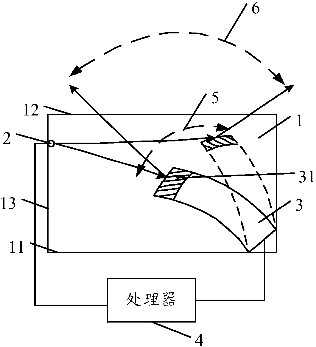
[0048] see figure 1 , is a schematic structural diagram of a projection device provided by an embodiment of the present invention. The projection device provided by the embodiment of the present invention includes: a projection chamber 1 , a light source 2 , a scanning motor 3 and a processor 4 .

[0049] In a specific implementation, the projection cavity 1 mentioned above may include a cylindrical projection cavity, a cube projection cavity, a cuboid projection ...


PUM


Abstract

The embodiment of the present invention discloses a projection device, comprising: a projection cavity, a light source, a scanning motor and a processor; the light source and the scanning motor are located inside the projection cavity, and the processor is respectively connected with the light source and the The scanning motor is connected; the scanning mirror of the scanning motor is provided with a reflective layer, and the reflective layer is used to reflect the light emitted by the light source. The embodiment of the present invention has the advantages that the reflection range of light can be enlarged and the projection angle of view can be enlarged.

Description

technical field [0001] The present invention relates to the field of electronic technology, in particular to a projection device and method. Background technique [0002] Currently, the near-eye light field display is used in Augmented Reality (AR for short) and Virtual Reality (VR for short) technologies, which can bring more realistic 3D display effects and become the development trend of 3D display technology in the future. . In light field display technology, wide view angle micro-projection devices are the basic components for generating light fields, and are being researched by many manufacturers. In a digital light processing (Digital Light Processing, DLP) system, the size of the digital mirror device (Digital Mirror Device, DMD) determines the size of the projection field of view (Field Of View, FOV), that is, the larger the size of the DMD, the larger the projection The larger the FOV, the smaller the size of the DMD and the smaller the projected FOV. However, t...

Claims


Application Information

Patent Timeline
Patent Type & Authority Patents(China)
IPC IPC(8): G03B21/20G03B21/14
CPCG03B21/142G03B21/206G03B21/2066A61B1/00172H04N9/3129H04N9/14G02B5/0808G02B26/105G02B27/0172H04N9/3194H04N9/3135
Inventor 林涛
Owner HUAWEI TECH CO LTD
Why Eureka
Try Eureka