
Ultra-precise straightness measuring method based on single-measuring-head error separation

A technology of error separation and measurement method, which is applied in the field of measurement application, can solve problems such as parabolic cumulative error, thermal drift measurement influence, difficult and high-precision spacing, etc., to eliminate the influence of zeroing error, avoid the influence of thermal drift, and scan the range. Effect

Inactive Publication Date: 2015-01-21
NAT UNIV OF DEFENSE TECH
View PDF5 Cites 14 Cited by
  • Summary
  • Abstract
  • Description
  • Claims
  • Application Information

AI Technical Summary

Problems solved by technology

However, when using multi-probe scanning measurement, there will be the following problems: 1. The zero-adjustment error of each probe will introduce a parabolic cumulative error, the larger the scan size, the more significant the impact, and the zero-adjustment error is difficult to achieve high precision Calibration; 2. The distance between multiple probes will deviate from the ideal position due to the influence of installation hole distance, aperture, probe outer diameter accuracy and clamping force, and the actual distance is difficult to measure with high precision. The spacing error will also affect the reconstruction accuracy of the measured surface profile. When scanning large-sized parts or measuring with high lateral resolution, this error will have a great impact; 3. The characteristic difference between different probes will also lead to reconstruction error
In actual measurement, sometimes it is difficult for the workpiece under test to be flipped or dislocated, so these two methods are difficult to implement; and since at least two scans are required, the repeatability of the slide will also affect the measurement results
In addition, the relative vibration between the measured surface and the probe, and when the measurement time is long, the thermal drift of the probe will have a greater impact on the measurement

Method used


Image

  • Ultra-precise straightness measuring method based on single-measuring-head error separation
  • Ultra-precise straightness measuring method based on single-measuring-head error separation
  • Ultra-precise straightness measuring method based on single-measuring-head error separation

Examples


Embodiment 1

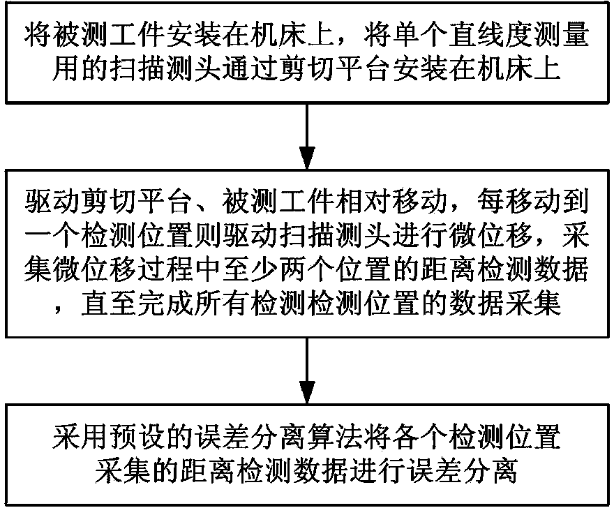
[0031] Such as figure 1 As shown, the implementation steps of the ultra-precise straightness measurement method based on single probe error separation in this embodiment are as follows:

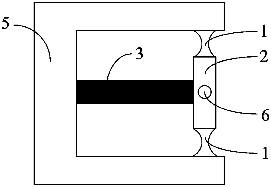
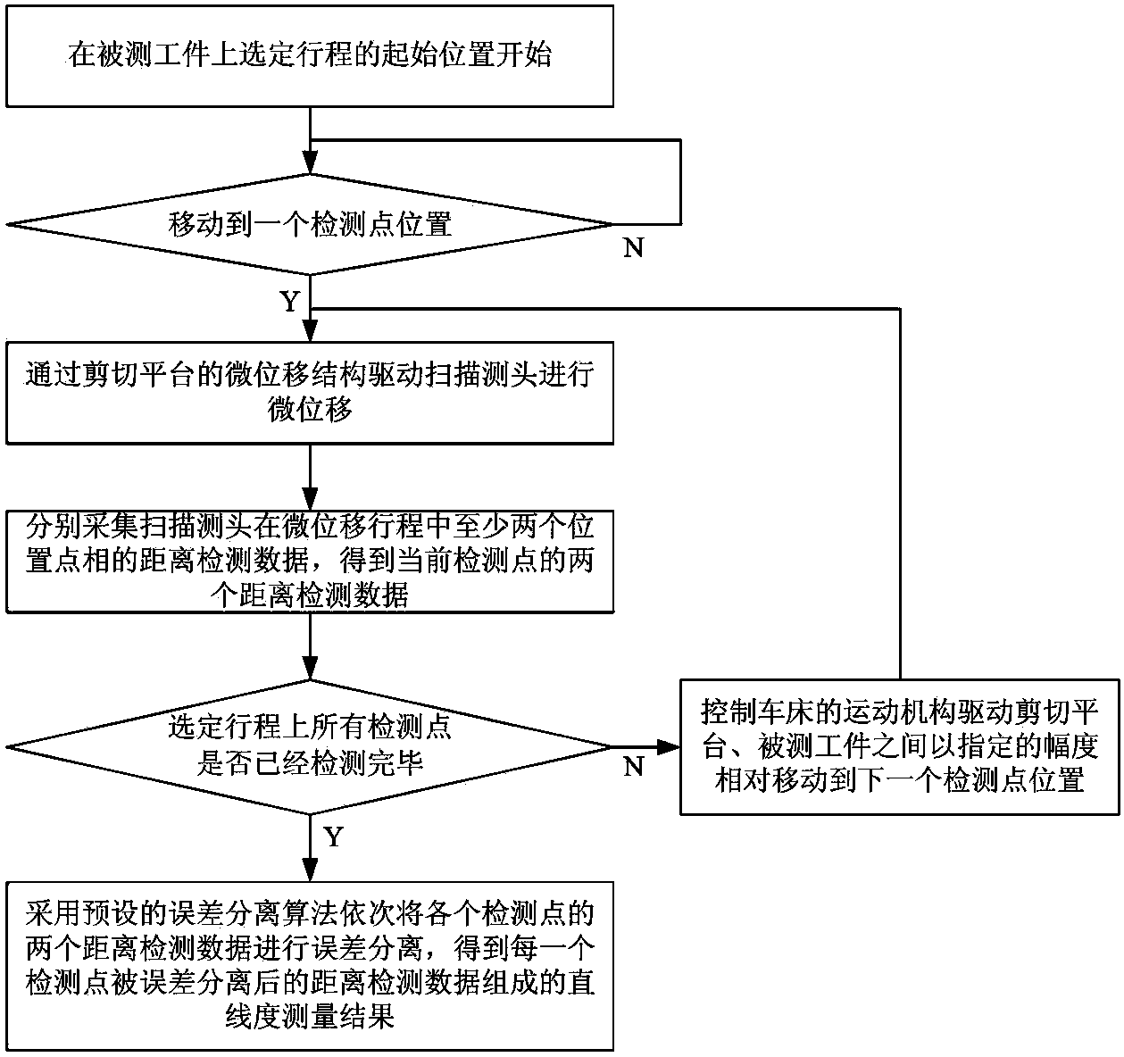
[0032]1) Install the workpiece to be measured on the machine tool, install the single scanning probe for straightness measurement on the machine tool through the shearing platform with micro-displacement structure, and drive the workpiece or the shearing platform to realize shearing through the kinematic mechanism of the machine tool. The relative movement between the cutting platform and the measured workpiece. For the shearing platform and the workpiece to be tested, the large-scale linear scanning motion can be realized by the motion mechanism of the machine tool to drive the workpiece to be tested or the shearing platform to realize the relative movement between the shearing platform and the workpiece to be measured, which can be done by the workpiece. Linear motion or shearing platform ...

Embodiment 2

[0046] This embodiment is basically the same as Embodiment 1, the difference being that the structure of the machine tool used in step 1) is different.

[0047] Such as Figure 6 As shown, the machine tool used in this embodiment is a diamond lathe with a C-axis function in a horizontal structure. The diamond lathe with a C-axis function has an XZ two-axis motion function, including a machine tool body 4, which is provided with an X Axis direction movement mechanism 41 and Z axis direction movement mechanism 43, X axis direction movement mechanism 41 is provided with a rotatable main shaft 8 (C axis), the workpiece 7 to be measured is mounted on the main shaft 8, and the scanning probe 6 has a micro-displacement The shearing platform 5 of the structure is installed on the moving mechanism 43 in the Z-axis direction. The shearing platform 5 is installed on the Z-axis direction movement mechanism 43 (where the diamond tool is installed), and moves horizontally with the Z-axis t...


PUM


Abstract

The invention discloses an ultra-precise straightness measuring method based on single-measuring-head error separation. The method comprises the implementing steps that a measured workpiece is placed on a machine tool, and a scanning measuring head is mounted on a movement mechanism of the machine tool through a shearing platform provided with a micro-displacement structure; starting from the starting position of a selected moving distance, the movement mechanism is controlled to drive the scanning measuring head to conduct amplitude -limited movement, and every time the scanning measuring head is moved to a detection position, the scanning measuring head is driven by the shearing platform to conduct micro-displacement to collect distance detection data of at least two positions in the micro-displacement process until data acquisition of all detection positions of the measured workpiece at the selected moving distance is completed; the distance detection data collected at all the detection positions are subjected to error separation through a preset error separation algorithm to obtain a straightness measuring result. The method has the advantages that measurement accuracy is high, the scanning area is large, the measuring range is large, measurement is convenient and fast, influences of environmental low-frequency vibration can be suppressed, and influences of zero setting errors, spacing errors, property difference and thermal drift of the measuring head are eliminated.

Description

technical field [0001] The invention relates to the technical field of measurement applications, in particular to an ultra-precision straightness measurement method based on single-probe error separation, which is mainly applied to the straightness, flatness, ultra-precision optical surfaces and even optical free-form surfaces of precision and ultra-precision workpiece surfaces The measurement of surface shape can also detect the straightness error of the motion platform. Background technique [0002] In precision and ultra-precision machining, in order to measure the straightness motion error of the guide rail, the straightness profile, flatness and surface shape accuracy of the workpiece surface, etc., the scanning measurement method is often used. This method uses the displacement probe (commonly used non- Contact sensors (such as capacitance or eddy current, etc.) or angle detectors (such as autocollimators, etc.) are installed on a mobile platform and move linearly alon...

Claims


Application Information

Patent Timeline
Patent Type & Authority Applications(China)
IPC IPC(8): G01B21/24
CPCG01B21/24
Inventor 尹自强李圣怡陈善勇陈涵田富竟
Owner NAT UNIV OF DEFENSE TECH
Learn More