Small optical resolution photoacoustic microscope based on micro-electromechanical scanning galvanometer

A technology of micro-electromechanical scanning and photoacoustic microscopy, which is applied in the direction of material analysis, scientific instruments, and analytical materials through optical means, can solve the problems of inability to apply endoscopic imaging, image quality loss, and volume reduction, and achieve easy application and promotion, reduced size and weight, high precision effect

Inactive Publication Date: 2018-04-20
UNIV OF ELECTRONICS SCI & TECH OF CHINA
View PDF5 Cites 14 Cited by
  • Summary
  • Abstract
  • Description
  • Claims
  • Application Information

AI Technical Summary

Problems solved by technology

However, these scanning mechanisms are usually bulky and heavy, and it is still difficult to meet the urgent needs of small and lightweight portable imaging systems in many medical applications.
[0003] In response to the above problems, many research groups at home and abroad have proposed many solutions, such as using a magnetically driven scanning mirror to simultaneously scan the focused laser beam and ultrasonic waves to achieve two-dimensional scanning, so as to build a set of miniaturized optical resolution lasers. Compared with the traditional photoacoustic microscope with optical resolution, the volume of the acoustic microscope has been reduced to a certain extent, and it can be hand-held, but it is still relatively bulky and has a large loss in image quality, so it still cannot be applied to endoscopic imaging and oral inspection. And applications such as brain imaging of freely moving small living animals

Method used


Image

  • Small optical resolution photoacoustic microscope based on micro-electromechanical scanning galvanometer
  • Small optical resolution photoacoustic microscope based on micro-electromechanical scanning galvanometer
  • Small optical resolution photoacoustic microscope based on micro-electromechanical scanning galvanometer

Examples


Embodiment 1

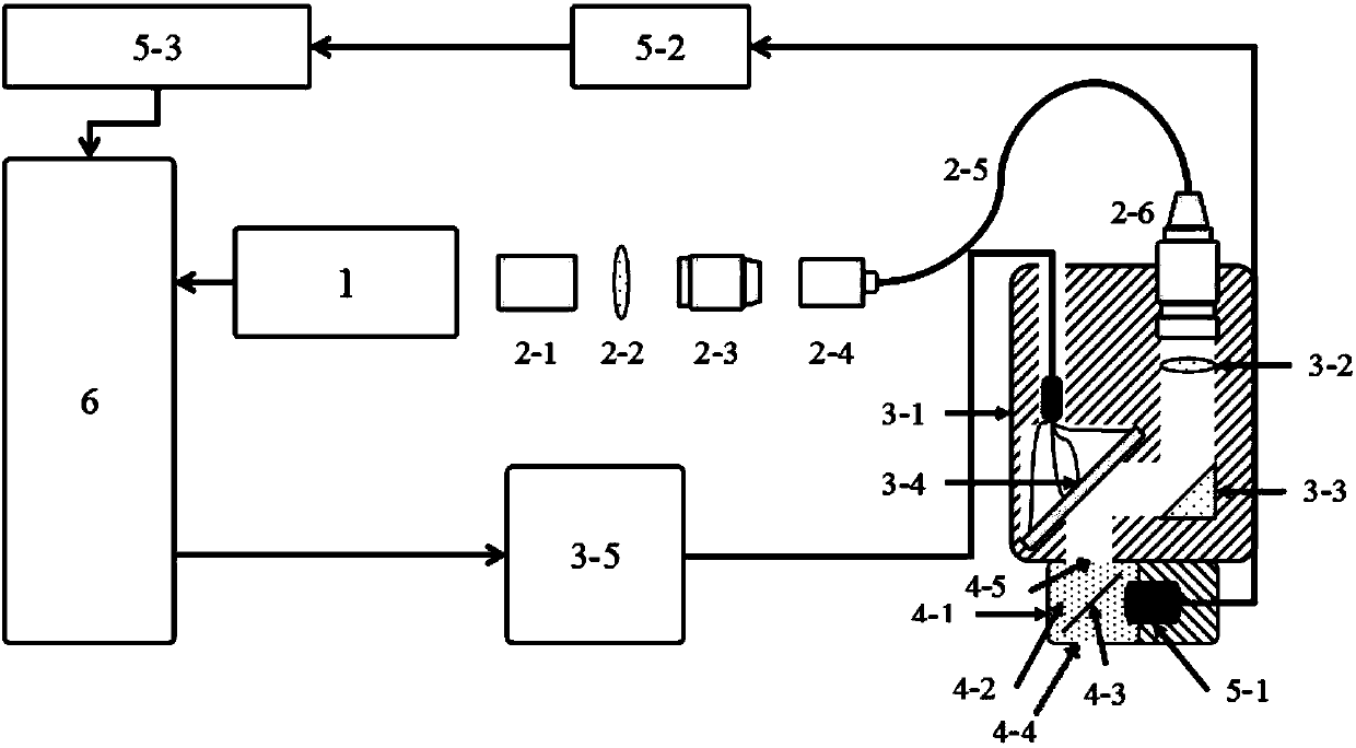
[0024] Such as figure 1 Shown is a schematic structural diagram of a small optical resolution photoacoustic microscope based on a MEMS scanning galvanometer provided in this embodiment, including a light source component, a single-mode fiber optical coupling component, a beam scanning component, a signal acquisition component and a computer, wherein, The light source assembly consists of a pulsed laser 1, which is electrically connected to a computer 6. The pulsed laser 1 is used to generate a pulsed laser with a pulse width between 1ns-10ns, a repetition frequency between 1Khz-100Khz, and a wavelength determined according to the imaging target. The spatial optical filter 2-1, the collimating lens 2-2, the objective lens 2-3, the single-mode fiber coupling adjustment frame 2-4 in the single-mode fiber coupling assembly are installed coaxially with the pulse laser 1 in turn, and pass through the single-mode fiber 2-5 and single-mode optical fiber collimating lens 2-6 are connec...

Embodiment 2

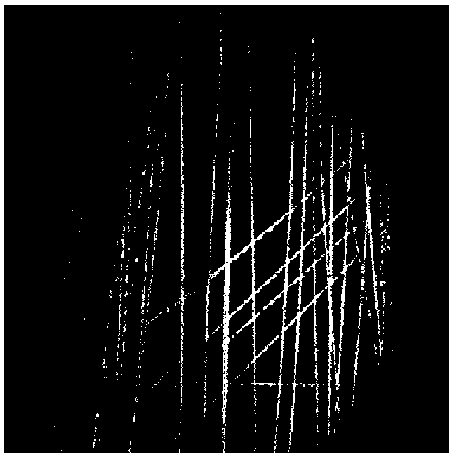
[0029] Example 2 Application of the method and device of the present invention to imaging carbon fiber filaments embedded in agar

[0030] Utilize the device of Example 1 to image the carbon fiber filaments buried inside the agar, wherein the wavelength of the pulsed laser output is 532nm, the pulse width is 2ns, the repetition frequency is 2000Hz, the scanning range is 2.5mm, and the scanning step is 5 μm, and a total of 500 samples are collected. group signals, obtained as figure 2 From the image shown, it can be seen from the image that the carbon fiber filaments in the agar can be clearly observed, indicating that the method and device of the present invention can obtain clear imaging of the target object in a relatively large imaging area.

Embodiment 3

[0031] Example 3 Application of the method and device of the present invention to imaging of living mouse ear blood vessels

[0032] Utilize the device of embodiment 1 to carry out imaging to living mouse ear blood vessel, wherein the wavelength of pulse laser output is 532nm, pulse width 2ns, repetition frequency 2500Hz, two-dimensional scanning galvanometer system scans along the diameter of imaging area, and scanning range is 2.5 mm, with a scan step of 5 μm, a total of 500 sets of signals were collected, and the following image 3 As shown in the image, it can be seen from the image that the capillaries in the ear of the living mouse are clearly presented, indicating that the method and device of the present invention can image the target object with a high resolution.

[0033] The present invention utilizes the microelectromechanical scanning galvanometer in the photoacoustic microscope with optical resolution, which can greatly reduce the volume of the system. In this em...


PUM


Abstract

A small optical resolution photoacoustic microscope based on a micro-electromechanical scanning galvanometer belongs to the technical fields of automatic control and imaging. The small optical resolution photoacoustic microscope includes a light source assembly, a single-mode fiber coupling assembly, a light beam scanning assembly, a reflective support 4-1, a signal acquisition assembly and a computer, the computer controls pulsed laser emitted from the light source assembly to be collimated by the single-mode fiber coupling assembly and then enter the light beam scanning assembly, the light beam scanning assembly includes the micro-electromechanical scanning galvanometer 3-4 and a function generator 3-5, the computer controls the micro-electromechanical scanning galvanometer 3-4 to rotatethrough the function generator 3-5, the pulsed laser entering the light beam scanning assembly is reflected by the micro-electromechanical scanning galvanometer 3-4, and reacts with a target object through the reflective support 4-1 in order to generate a photoacoustic signal, and the photoacoustic signal is reflected by a light-transmitting and acoustic-reflecting sheet, is acquired by the signal acquisition assembly, is transmitted to the computer, and is stored and processed. The small optical resolution photoacoustic microscope has the advantages of small size, light weight, wide scanningrange and high scanning precision.

Description

technical field [0001] The invention relates to the technical field of automatic control and imaging, in particular to a small photoacoustic microscope with optical resolution based on a microelectromechanical (MEMS) scanning vibrating mirror. Background technique [0002] Optical resolution photoacoustic microscopy is a non-destructive medical imaging technology with high resolution and high contrast emerging in the past decade, which is widely used in various medical research. Different from traditional optical microscopes, optical-resolution photoacoustic microscopy needs to acquire images by point-by-point scanning, so a high-precision scanning mechanism is crucial for optical-resolution photoacoustic microscopy. At present, when applying optical resolution photoacoustic microscope to image the target object at home and abroad, the application of high-performance stepping motor or scanning galvanometer is the most common method to achieve high-precision scanning. Howeve...

Claims


Application Information

Patent Timeline
Patent Type & Authority Applications(China)
IPC IPC(8): G01N21/17
CPCG01N21/1702
Inventor 奚磊陈倩齐伟智
Owner UNIV OF ELECTRONICS SCI & TECH OF CHINA
Why Eureka
Try Eureka