
Charging Post Controller with Functional Modules Connected by Means of PCB, and Charging Post Thereof

Pending Publication Date: 2022-03-03
SICHUAN WEIYU ELECTRIC CO LTD
View PDF0 Cites 0 Cited by
  • Summary
  • Abstract
  • Description
  • Claims
  • Application Information

AI Technical Summary

Benefits of technology

The charging post controller in this patent has a compact structure and small size, making it easier to install and reducing the need for manual wiring. The monitoring unit and direct-current main loop unit are integrated on a mounting and fixing unit, which simplifies the manufacturing process, reduces costs, and improves production efficiency. The various functional modules in the monitoring unit are connected by a PCB, eliminating the need for independent shells and mutual connections between terminals. This improves reliability and safety, reduces wasted space, and simplifies production assembly. Overall, this design provides a more streamlined and efficient production process.

Problems solved by technology

The comprehensive costs of charging posts directly affect the application and development of electric vehicles.
In this way, various control modules and / or low-voltage electrical components are packaged separately, and occupy great space in the charging post, leading to great workloads in processing and assembling cabinets, and increasing an investment in the hardware cost when the charging post is made.
Meanwhile, electrical connection between various devices is completed with the manner of greatly manual cable wiring, which enjoys a complicated process, and is greatly affected by human factors, leading to high human resource costs of the charging post and long production cycles, and also readily leading to low production efficiency and reliability of the charging post.
In summary, a technical solution is badly needed at the current stage to solve the technical problems, namely, various devices in an existing charging post are provided separately, electrical connection is carried out with the manner of manual cable wiring, which is a complicated process, leading to high investments in hardware cost and human resource cost of the charging post, and long production cycles, and low production efficiency and reliability.
The object of the present utility model lies in: various functional modules in an existing charging post are provided independently, and are electrically connected with each other with the manner of manual cable wiring, presenting a complicate process, leading to the technical problems, namely, high investments in hardware cost and human resource cost of the charging post, and long production cycles, and low production efficiency and reliability, and providing a charging post controller with various functional modules connected by means of a PCB, and a charging post thereof.
Convenience of the terminal further reduces the difficulty in assembling the charging post.

Method used


Image

  • Charging Post Controller with Functional Modules Connected by Means of PCB, and Charging Post Thereof
  • Charging Post Controller with Functional Modules Connected by Means of PCB, and Charging Post Thereof
  • Charging Post Controller with Functional Modules Connected by Means of PCB, and Charging Post Thereof

Examples


example 1

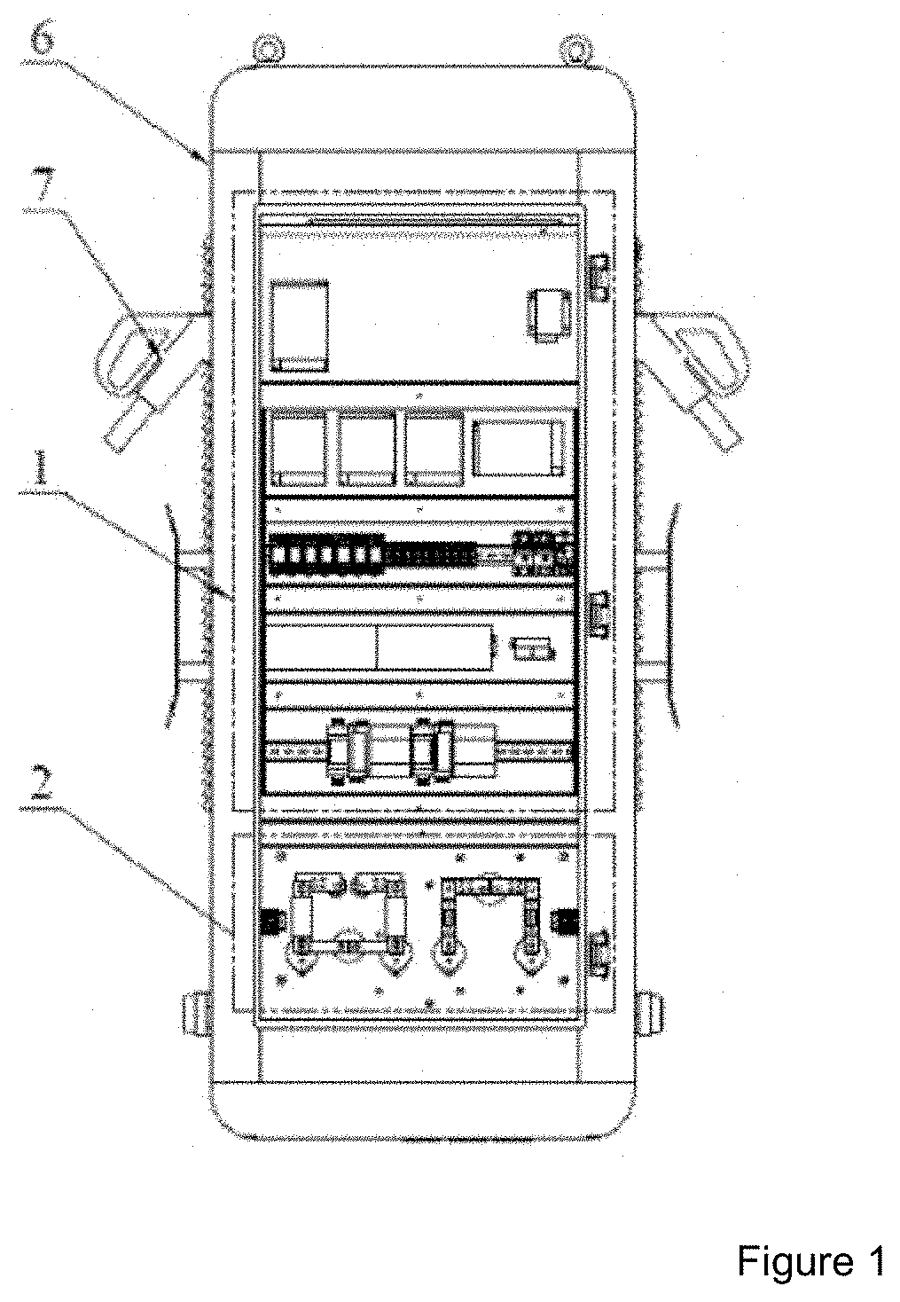
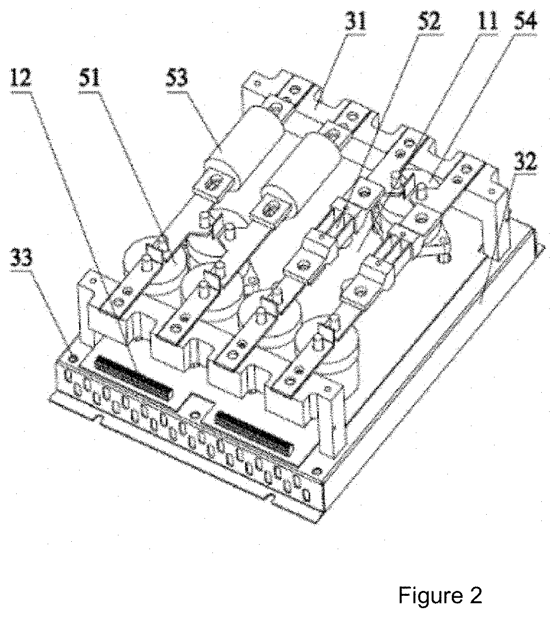
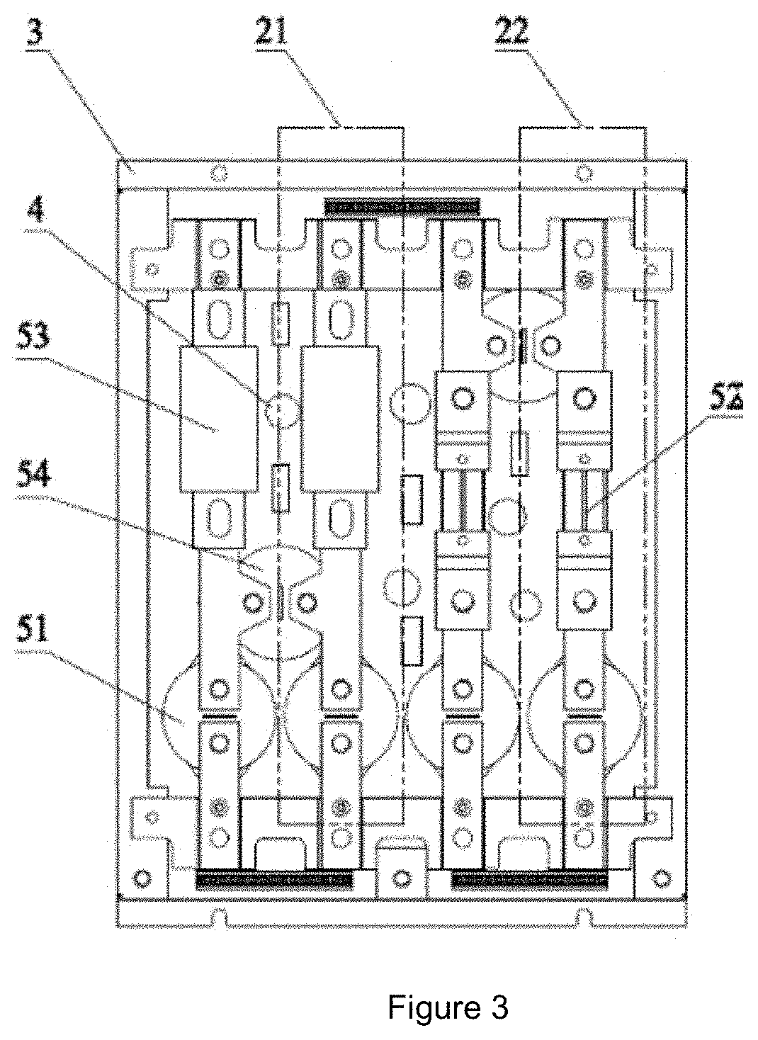
[0048]As shown in FIGS. 2-6, a charging post controller with various functional modules connected by means of a PCB comprised a monitoring unit 1, a direct-current main loop unit 2 and a mounting and fixing unit 3 associated with each other. A laminated arrangement structure was formed between the monitoring unit 1, the direct-current main loop unit 2, and the mounting and fixing unit 3. The monitoring unit 1 comprised several functional modules 4 formed by combining a PCB 11 and an electronic circuit, the functional modules 4 being electrically connected by means of the PCB 11. The several functional modules 4 were mounted on one face or two faces of the mounting and fixing unit 3. The direct-current main loop unit 2 comprised several unit modules 5 connected with copper bars and / other non-wiring manner. Various unit modules 5 were mounted on a face or two faces of the monitoring unit 1.

[0049]As for the charging post controller with various functional modules connected by means of ...

example 2

[0057]As shown in FIGS. 2-8, the charging post controller with various functional modules connected by means of a PCB in the Example had the same structure as that in Example 1, and they differed from each other in: the electronic circuits of various functional modules 4 of the monitoring unit 1 were integrated on a PCB 11, and were electrically connected with each other by means of tracing within the PCB 11.

[0058]As for the charging post controller with various functional modules connected by means of a PCB in the Example, the controller had a higher degree of integration and more convenient assembling by integrating the electronic circuits of functional modules of the monitoring unit 1 on a PCB 11. The electronic circuits of a plurality of monitoring units 1 were preferably integrated on a PCB 11, realizing monitoring of the charging states of a plurality of charging guns 7.

[0059]Preferably, various functional modules of the monitoring unit 1 were provided on multiple PCBs 11 whic...

example 3

[0060]As shown in FIGS. 2-11, a charging post controller with various functional modules connected by means of a PCB in the Example had the same structure as that in Example 1, and they differed from each other in: the direct-current main loop unit 2 comprised a positive component and a negative component. The positive component comprised at least one positive path 21 for connecting a charging module cathode and a power consumption cathode, and the negative component comprised at least one negative path 22 for connecting a charging module anode and a power consumption anode. The positive path 21 and the negative path 22 were arranged according to the cathode side and the anode side. The positive path 21 and the negative path 22 matched with each other, forming one or more charging loops.

[0061]With a charging post controller with various functional modules connected by means of a PCB in the Example, preferably, the positive path 21 and the negative path 22 were provided in parallel b...


PUM


Abstract

A charging post controller with various functional modules connected by means of a PCB, and a charging post thereof. The controller comprises a monitoring unit (1), a direct-current main loop unit (2) and a mounting and fixing unit (3), wherein the monitoring unit (1) comprises several functional modules (4) formed by combining a PCB (11) and an electronic circuit, the functional modules (4) are electrically connected by means of the PCB (11), and the several functional modules (4) are mounted on the mounting and fixing unit (3), such that a laminated arrangement structure is formed among the monitoring unit (1), the direct-current main loop unit (2) and the mounting and fixing unit (3), thereby making the controller compact in structure, reducing the loss of transmission lines, increasing the power density, improving the reliability and safety of usage and allowing a relatively good working effect; moreover, the manual wiring work in a preparation process of the controller is reduced, assembly line production can be realized, the production cost is reduced, and the production efficiency is improved; and the charging post using the controller has a relatively high degree of integration, relatively small overall volume and relatively low comprehensive cost, and is relatively easily promoted and applied.

Description

TECHNICAL FIELD[0001]The present utility model relates to the technical field of charging posts, and relates to a charging post controller connected with various functional modules connected by means of a PCB, and a charging post thereof in particular.BACKGROUND ART[0002]With the development of new energy vehicles, use of electric vehicles is drawing more and more attentions from people. A charging post is an indispensable supporting device for normal use of electric vehicles, and is a key technology for developing the electric vehicles. The comprehensive costs of charging posts directly affect the application and development of electric vehicles.[0003]FIG. 1 is a schematic diagram of the inner structure of a charging post with two charging guns in the current arrangement. For ensuring normal operation of the charging post, a monitoring unit and a direct-current main circuit unit electrically connected with each other are provided in the charging post at the same time. Monitoring fu...

Claims


Application Information

Patent Timeline
IPC IPC(8): H02J7/00B60L53/31B60L53/14
CPCH02J7/0042B60L53/14B60L53/31H02J7/0047B60L53/60Y02T10/70Y02T10/7072Y02T90/12Y02T90/14
Inventor LIU, SHAODECHEN, XIAOFAHUANG, GANG
Owner SICHUAN WEIYU ELECTRIC CO LTD
Learn More