Method and apparatus for uplink signal transmission and channel estimation in wireless access network

Inactive Publication Date: 2011-07-07
ALCATEL LUCENT SAS
View PDF14 Cites 25 Cited by
  • Summary
  • Abstract
  • Description
  • Claims
  • Application Information

AI Technical Summary

Benefits of technology

[0034]This invention is also intended to provide the above mentioned method and apparatus which can guarantee a relatively high antenna power gain.
[0035]This invent

Problems solved by technology

Due to the independency of each user channel in the MU-MIMO system, the user can get to know about its own channel state information, but can hardly obtain the channel state information of the other users, and the obtaining of the channel state information of the other users requires great cost.
That is to say, it is hard to conduct cooperation between users.
Of course, if combined with the realization problem of the practical application, the complexity of the algorithm should also be considered, thus a compromise between the performance and the complexity needs to be found.
It could be said so, that the complexity is the price for the numerous advantages introduced by the Multi-User MIMO technology.
However, it has always been difficult for the user terminal to implement the settlement of the multiple antennas, and it is unrealistic to satisfy the idea

Method used


Image

  • Method and apparatus for uplink signal transmission and channel estimation in wireless access network
  • Method and apparatus for uplink signal transmission and channel estimation in wireless access network
  • Method and apparatus for uplink signal transmission and channel estimation in wireless access network

Examples


Embodiment Construction

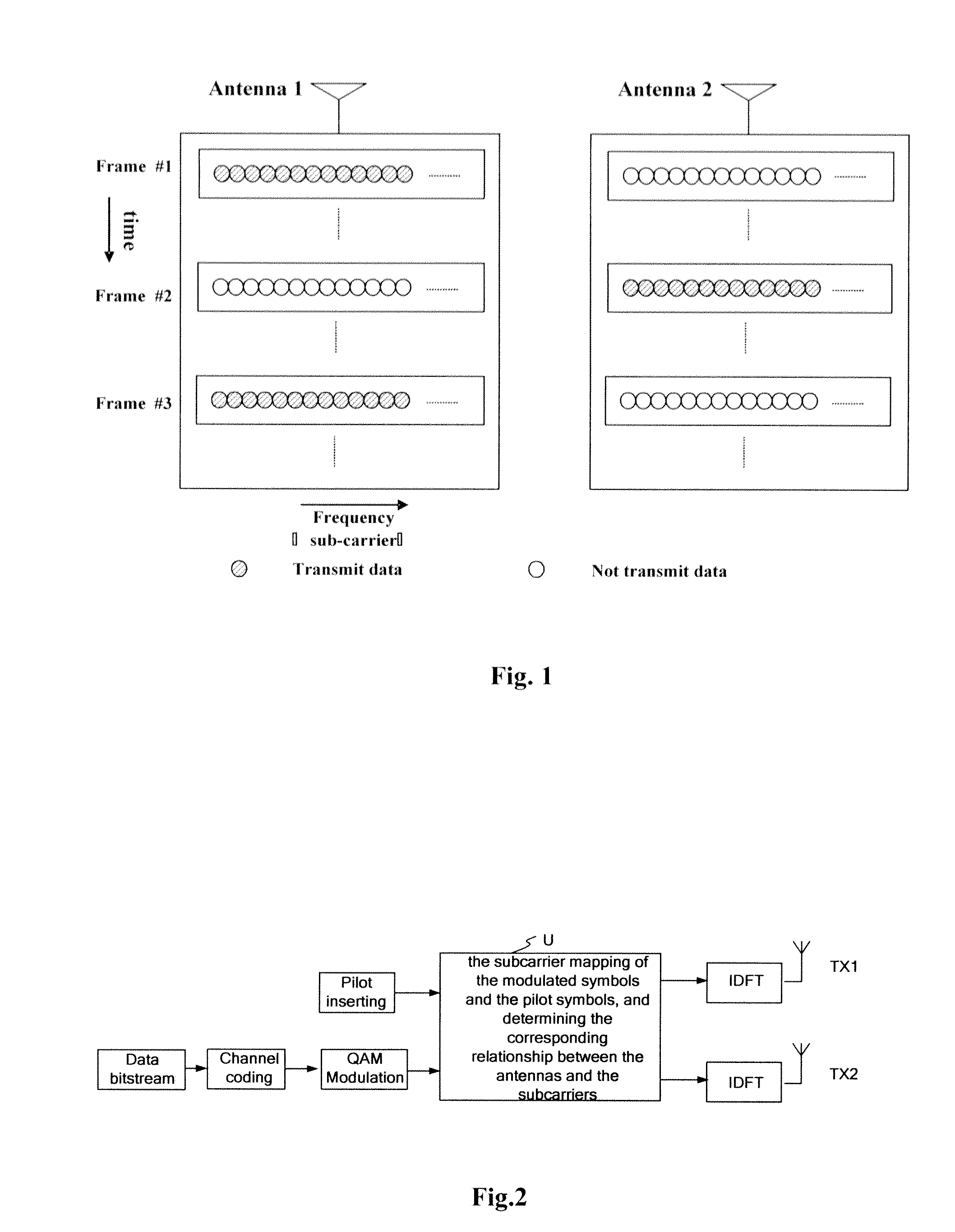
[0055]FIG. 2 shows a sketch of the physical layer of a transmitter according to one embodiment of the invention. Since only the uplink signal transmission is discussed in the present invention, the transmitter is mainly located in the various network devices needing to transmit uplink signal in a wireless manner in the access network, such as mobile terminal, relay station, etc. Of course, with the development of the wireless transmission technology, if the base station needs to transmit uplink wireless signal in the near further, the transmitter shown in the figure may also be used in the base station. In the following, without loss of generality, the present invention will be described using the uplink communication between the mobile terminal and the base station as example.

[0056]It should be understood by those skilled in the art, some modules that should be included in the Orthogonal Frequency Division Multiplexing (OFDM) transmitter, such as module for inserting Cyclic Prefix ...


PUM


Abstract

The present invention provides a new method and apparatus, in a network device of a multi-carrier based wireless access network, for transmitting uplink data to access device side, and the corresponding method and apparatus for channel estimation in its uplink counterpart device, wherein, a plurality of network device comprise one or more multi-antenna network devices, at least one of the multi-antenna network device transmits multipath subcarrier modulated symbols via a plurality of transmitting antennas configured for itself, wherein, at least two transmitting antennas use different subcarrier sets, but share one pilot pattern, wherein, pilot pattern used by each network device is different from the pilot pattern used by any other network device. The present invention not only can fully utilize the frequency diversity introduced by the plurality of transmitting antennas, but also can guarantee a relative high antenna power gain and save as much time-frequency resource cost caused by pilot signal as possible.

Description

FIELD OF THE INVENTION[0001]The present invention relates to a multi-carrier based wireless access network, in particular relates to the uplink data transmission and the processing of the uplink communication in a multi-carrier based wireless access network.BACKGROUND OF THE INVENTION[0002]Multi-User Multiple-Input Multiple-Output (MU-MIMO)[0003]The uplink of the MU-MIMO is typically referred to as Multiple Access Channel (MAC), and the downlink is referred to as Broadcast Channel (BC). In the uplink, all mobile terminals work at the same frequency band and transmit signals to the base station simultaneously, and then the base station distinguishes user data in a proper manner. The base station needs to separate data of each user by using array processing, multi-user detection or other effective manner aiming at different access manners. In the downlink, the base station performs serial-parallel conversion to the processed data so as to generate a plurality of data streams, each of ...

Claims


Application Information

Patent Timeline
IPC IPC(8): H04J1/16H04J1/02
CPCH04L5/0023H04L25/0224H04L5/006H04L5/0051
Inventor ZHU, XIAOLONGSONG, YANG
Owner ALCATEL LUCENT SAS
Why Eureka
Try Eureka