
Eureka
For R&D, Eureka makes reading and utilizing patents & technical documents easy.
Eureka AIR
Designed for self-driven R&D workflows. Generate viable solutions, solve complex R&D challenges, empower your innovation with AI.

Eureka Materials
Designed for material experts only. Revolutionize your material R&D, from search, analyze, to developing new materials.

TechResearch
Generate reliable direction feasibility study reports for your R&D in just a few steps.

TechSeek
Discover and master advanced knowledge NOW. Basics, ideas, possibilities, all at once.

TechMind
As an expert in R&D Theories, TechMind can generates customized viable solutions instantly.

TechRisk
Analyze your overall solution with one click, know your potential R&D risks in advance.

TechMonitor
Get weekly tech updates, stay abreast of the latest tech innovations and key insights.
Distributed station, aggregation station, terminal, and communication method
- Summary
- Abstract
- Description
- Claims
- Application Information
AI Technical Summary
Benefits of technology
Problems solved by technology
Method used
Image

Examples
first exemplary embodiment
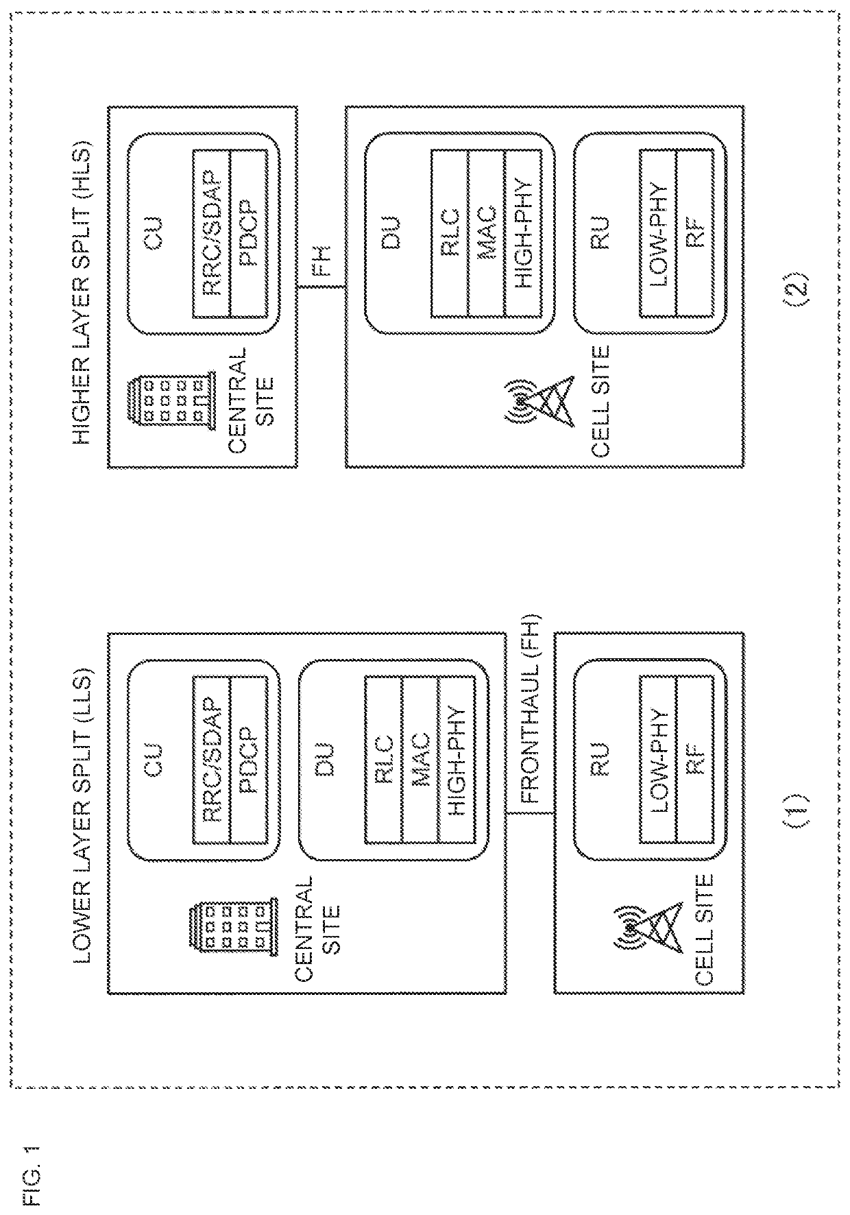
[0043]FIG. 1 is a diagram illustrating an arrangement example of functional modules of a base station. In 3GPP Release 15, a new interface and functional module are introduced as a 5th generation radio access network (5G RAN) architecture. For example, a 5th-generation new radio (5G NR) base station referred to as a gNB may be configured by three functional modules: a centralized unit (CU); a distributed unit (DU); and a radio unit (RU).
[0044]The CU may be referred to as, for example, a centralized node, an aggregation node, a centralized station, an aggregation station, or a centralized unit. The DU may be referred to as, for example, a distributed node, a distributed station, or a distributed unit. The RU may be referred to as, for example, a wireless device, a radio node, a radio station, an antenna unit, or a radio unit.
[0045]A plurality of arrangement configurations is considered for the three functional modules. Two configurations called a lower layer split (LLS) and a higher ...
second exemplary embodiment
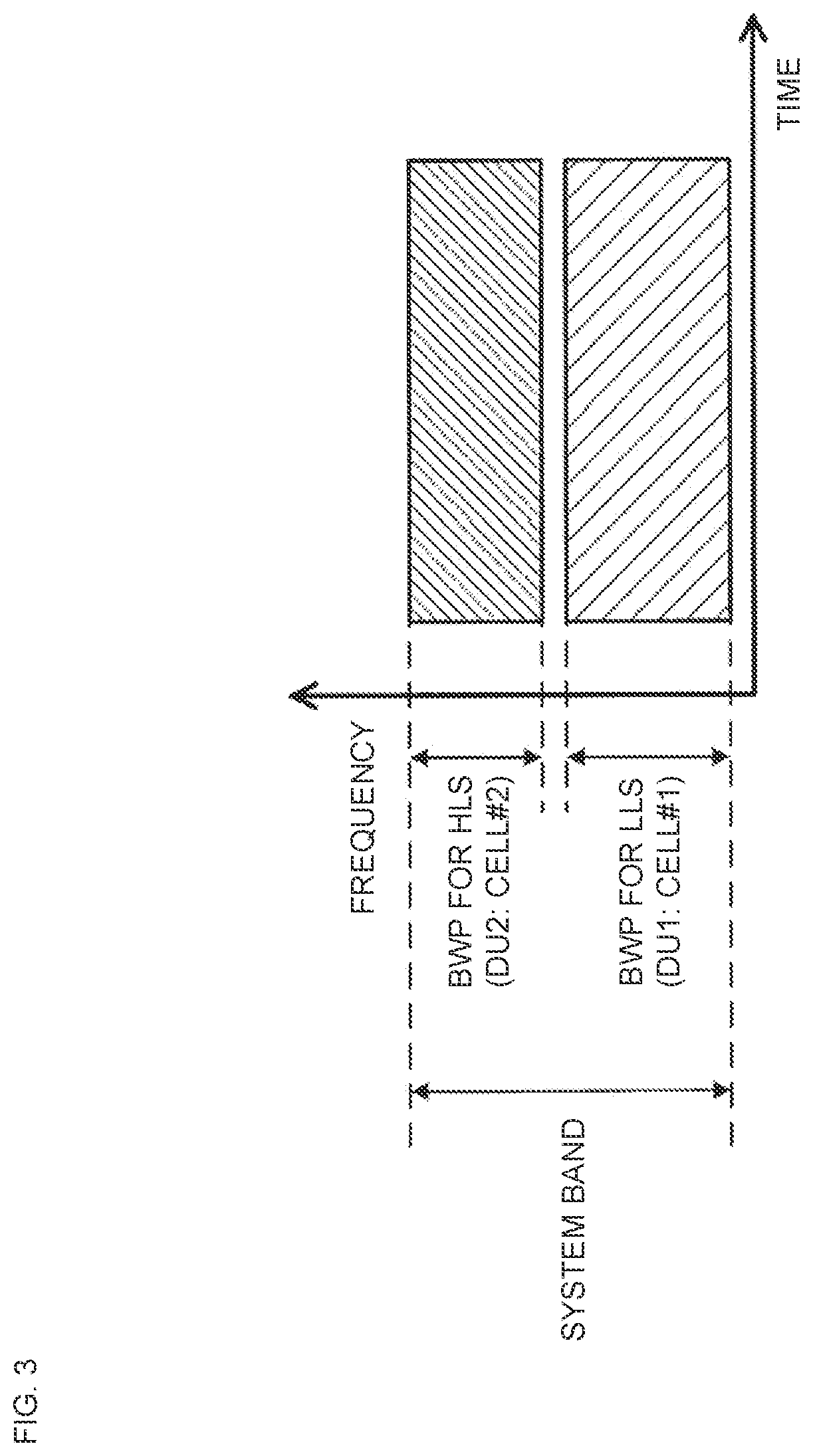
[0109]In the first exemplary embodiment, the signaling of the RU switching and the multiple BWP connection is performed by the L1 signaling or the L2 signaling, but in a second exemplary embodiment, this signaling is performed by L3 signaling. This enables the RU switching in the macro cell area and the multiple BWP connection as in the first exemplary embodiment, and thus enables the terminal to receive the low-delay service of DU2 in the small cell area early.
[0110]FIG. 11 is a diagram illustrating an example of a sequence of a wireless communication system according to the second exemplary embodiment. In FIG. 11, the same processing steps as those in FIG. 8 are denoted by the same reference numerals.
[0111]Processing in S1 to S5 illustrated in FIG. 11 is similar to the processing in S1 to S5 described with reference to FIG. 8, and the description thereof will be omitted. However, in S1 of FIG. 11, the terminal receives neighbor cell information (Cell #2) and does not receive infor...
third exemplary embodiment
[0122]In a third exemplary embodiment, a condition for triggering RU switching and a multiple BWP connection will be described.
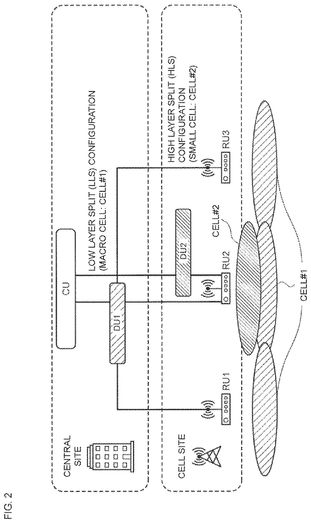
[0123]A terminal measures channel state information (CSI) as reception quality of a beam of each RU forming Cell #1 in the macro cell area. The terminal notifies a primary DU about a CSI report of the measured CSI.
[0124]The primary DU compares the reception quality of the beam of each RU in Cell #1 based on the notified CSI report. When the reception quality of a switched RU is high, the primary DU performs the RU switching and the multiple BWP connection. The primary DU may use, for example, the following condition 1 as a trigger condition for the RU switching and the multiple BWP connection.
(Reception level of beam of RU2 in Cell #1)>(Reception level of beam of RU1 (or RU3) in Cell #1) Condition 1
[0125]For example, in FIG. 6, the terminal measures the CSI of the beams of RU1, RU2, and RU3 forming Cell #1 in the macro cell area. The terminal notifies the p...
PUM
 Abstract
Description
Claims
Application Information
 - R&D Engineer
- R&D Manager
- IP Professional
- Industry Leading Data Capabilities
- Powerful AI technology
- Patent DNA Extraction
Browse by: Latest US Patents, China's latest patents, Technical Efficacy Thesaurus, Application Domain, Technology Topic, Popular Technical Reports.
© 2024 PatSnap. All rights reserved.Legal|Privacy policy|Modern Slavery Act Transparency Statement|Sitemap|About US| Contact US: help@patsnap.com