Anti-Predator Device for Beehive

a technology of anti-predator and beehive, which is applied in the field of anti-predator device for beehives, can solve the problems of reducing the entrance size, creating significant economic costs for the bee industry in general, and wasps entering the beehive, so as to reduce the incidence of beehive robbing, increase the volume of bee traffic, and increase the attack of host bees.

Pending Publication Date: 2022-03-10
BEE IQ SOLUTIONS LTD
View PDF8 Cites 0 Cited by
  • Summary
  • Abstract
  • Description
  • Claims
  • Application Information

AI Technical Summary

Benefits of technology

[0031]The invention thus provides a tunnel which is a space in which the freedom of movement of the pest is limited while the pest is trying to get into the hive. As a result there is increased chance of interaction between an invading pest and host bees, e.g. guard bees, compared with an unmodified beehive. The nature of the environment provided in the tunnel is more likely to feel threatening or otherwise elicit a stress-related reaction from the pest. Pheromones may as a result be released in increased amounts by the pest, which pheromones can alert host bees to the pest's presence. Either or both of these can raise the chance of encounters between pests and host bees and increase attacks on pests as they attempt to enter the hive; overall pest invasion into the hive is reduced and for those that do manage to enter the hive, pest escape is reduced.
[0032]In preferred embodiments, the tunnel comprises at least 2 sections, a first section in which bees must move substantially horizontally to advance towards the hive interior and a second section in which bees must move substantially vertically to exit the tunnel and gain access to the interior. In use, bees or pests entering the hive must do so in a non-linear way. The geometry of the tunnel promotes movement of the bees or pests first inwards and then upwards, preferably towards / into the cluster and promoting encounters between pests and hosts. The intruder may thus be naturally forced into engagement with the host and a release of stress pheromone may be initiated promoting further attack on the intruder creating an ongoing cycle of pheromone release and attack. Another consequence is that to exit the hive, bees or pests must do the reverse, and move downwards into the tunnel and then outwards. Generally, pests find exiting easier when they can see a visual clue of the outside world. For a pest not yet in the tunnel, however, it is preferred that there is no line-of-sight from any position inside the hive (NB, as mentioned, not yet in the tunnel) to the outside. A pest inside the hive cannot see the visual clue of the outside and so may be confused as to the location or direction of the exit. This prolongs pest time in the hive and increases the chance of encounter with and attack by host bees.
[0064]It is further optional to modify a hive, or provide a hive per se, with a plurality of tunnels of the invention, increasing the volume of bee traffic according to the needs of the season.
[0065]Preferably, in use, the tunnel is sufficiently elongated that when host bees are present invading bees or wasps or other pests entering the beehive encounter host bees to an increased extent compared with hives not having the tunnel, resulting in increased attacks by host bees on the invading pests and reduced incidence of beehive robbing by the invading pests, again compared with hives not having the tunnel.

Problems solved by technology

There is an additional problem of wasps entering a beehive to consume resources within the hive such as the bees themselves, larvae, honey and pollen stores, or supplementary feed sources.
However, during summer or other times of high bee numbers and productivity, a reduced entrance size is not practical as it is desirable to have a relatively large hive entrance to allow for the larger number of bees to enter and exit the hive.
Despite these preventative measures the problem of either total or partial beehive loss due to wasp activity creates a significant economic cost to the bee industry in general.
Various lures have been developed to capture wasps outside of hives, however their effectiveness is extremely inconsistent.
These appear to be more effective than lures, however the use of toxic poisons create their own set of challenges and user preferences.
A related problem is hive robbing not only by wasps but also by bees from neighbouring, competing hives, especially at times of dwindling resources such as towards the end of the honey season.

Method used


Image

  • Anti-Predator Device for Beehive
  • Anti-Predator Device for Beehive
  • Anti-Predator Device for Beehive

Examples


first embodiment

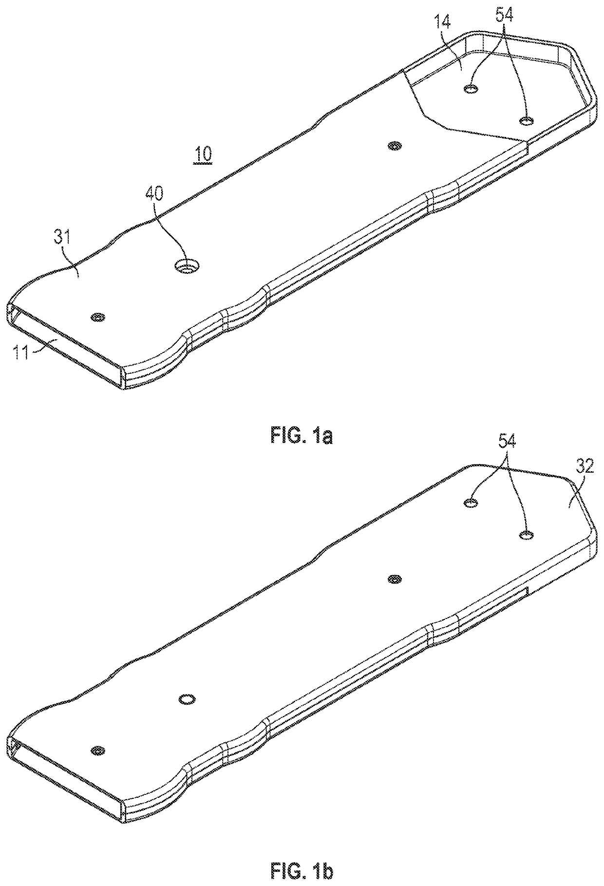
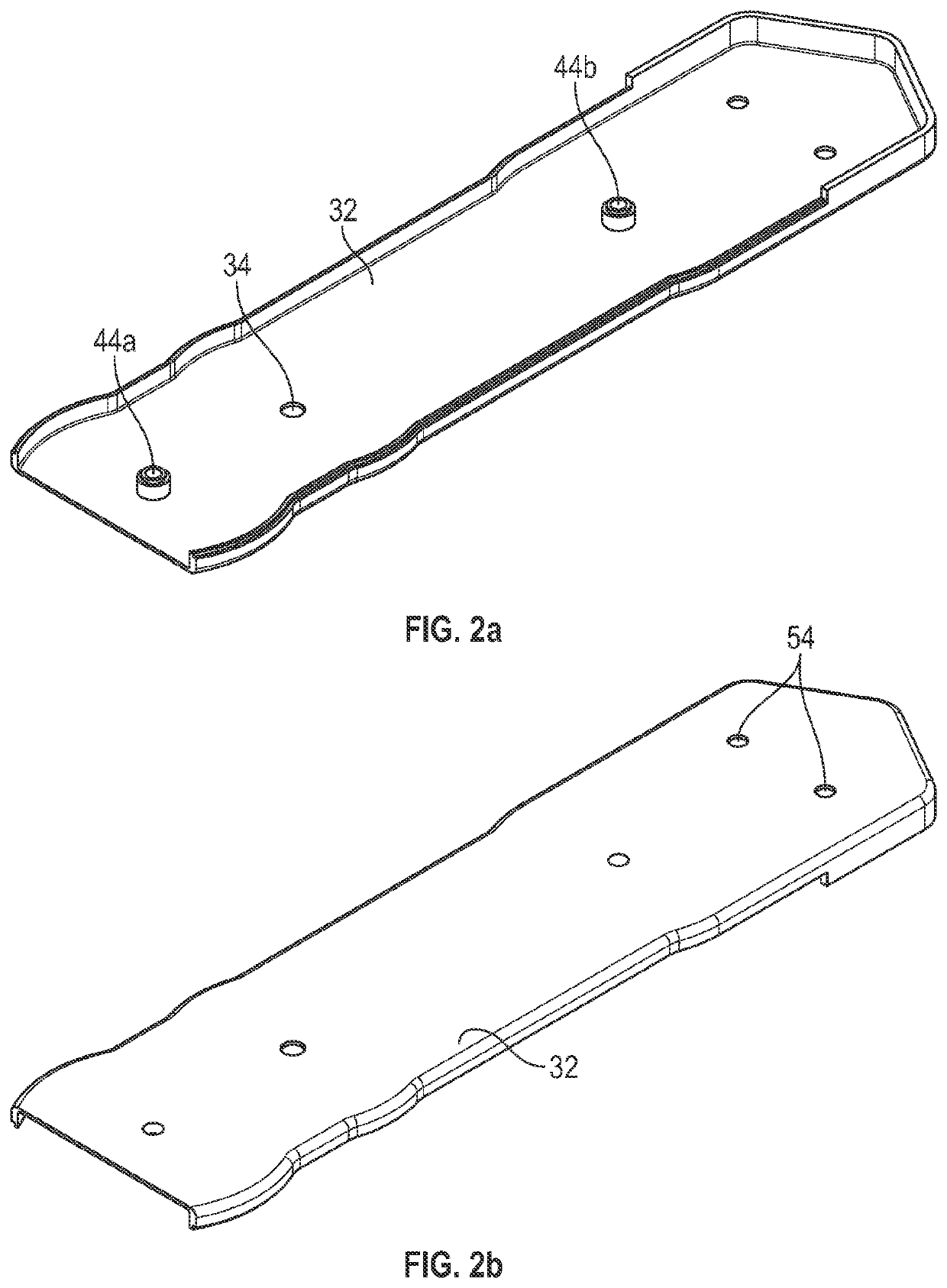
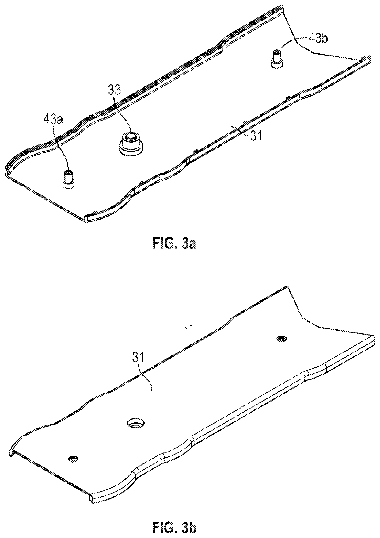
[0109]Referring in more detail to the figures, FIGS. 1a, 1b, 2a, 2b, 3a and 3b depict the invention (10) having an upper tunnel portion (31) and a lower tunnel portion (32). The tunnel has an entrance (11) and an exit (14). When the apparatus is in position on the bottom board of a beehive, the entrance (11) is positioned external to the beehive and the exit (14) internal to the hive. The exit (14) is in the upper surface of the apparatus to force pests attempting to enter the hive upwards into the cluster. The outer wall of the tunnel entrance (11) comprises a circular contour as a frusto-circular plan form (52) which is outwardly convex and arranged on opposing sidewalls. The tunnel further has drainage holes (54). The upper tunnel portion (31) and lower tunnel portion (32) are secured together by engaging a boss (33) in the upper tunnel portion (31) and a complementary aperture (34) in the lower tunnel portion (32). Once the boss (33) and aperture (34) are engaged, a nail or scre...

second embodiment

[0111]FIGS. 5, 6a and 6b show the invention (110) having a tunnel and comprising an upper tunnel portion (131) and a lower tunnel portion (132). The tunnel has an entrance (111) and an exit (114). The upper tunnel portion (131) and lower tunnel portion (132) have a flare (112) at the entrance (111), this allows the apparatus to be pivoted whilst maintaining a seal between the apparatus and the entrance to the beehive. The upper tunnel portion (131) and lower tunnel portion (132) are secured together by engaging a boss (133) in the upper tunnel portion (131) and a complementary aperture (134) in the lower tunnel portion (132). Once the boss (133) and aperture (134) are engaged, a nail or screw may be passed through the channel (140) formed by the engaged boss (133) and aperture (134) to fix the apparatus to the base of a beehive. This embodiment also depicts additional structure points comprising a structure boss (143a, b) in the upper tunnel portion (131) and a structure aperture (1...

third embodiment

[0112]FIG. 7 depicts the invention (210) having a tunnel, upper tunnel portion (231) and lower tunnel portion (232). The centre of the tunnel comprises a circular contour as a frusto-circular plan form (256) about the channel (240). The channel (240) blocks the centre of the tunnel, therefore the frusto-circular section (256) allows additional space for bees to pass around the channel (240) within the tunnel. FIG. 7 further shows how the apparatus can be rotated according to the arrows (257), whilst maintaining a seal between the flare (212) at the entrance (211) to the tunnel and the entrance to the beehive.


PUM


Abstract

The present specification discloses a beehive comprising (i) an exterior wall, (ii) a hive interior, and (iii) an entrance through the wall that allows access and egress of bees to and from the hive interior. A beehive disclosed herein can further comprise (iv) a beehive entrance tunnel having a proximal entrance end at the hive entrance and a distal exit end that extends into the hive interior. In operation, the bees enter the beehive by proceeding along the tunnel; wherein in use of the hive the tunnel is sufficiently elongated that when host bees are present invading pests, e.g. bees or wasps, entering the beehive via the tunnel encounter host bees in the tunnel resulting in attacks in the tunnel by host bees on the invading bees or wasps. Existing hives are modified so as to have such an entrance tunnel.

Description

[0001]This application is a 35 U.S.C. § 371 U.S. national stage patent application which claims the benefit of priority and is entitled to the filing date of International Patent Application PCT / EP2019 / 086673, filed Dec. 20, 2019, an application that claims the benefit of priority and is entitled to the filing date of NZ 749552, filed Dec. 21, 2018, the content of each of which is hereby incorporated by reference in its entirety.FIELD OF THE INVENTION[0002]The present invention relates to an anti-predator device for a beehive. More particularly but not exclusively the present invention relates to a hive entrance tunnel which defines a point of entry to a beehive designed to improve hive defence against pests, e.g. predator wasps and bees.BACKGROUND TO THE INVENTION[0003]A modern beehive for cultivating bees is generally in the form of a box with components that can be removed for inspecting the hive or accessing the honey. The box provides most of the structure of the hive and the b...

Claims


Application Information

Patent Timeline
Patent Type & Authority Applications(United States)
IPC IPC(8): A01K47/06A01K51/00
CPCA01K47/06A01K51/00
Inventor ATKINSON, KYLE BLAIR WAYNE
Owner BEE IQ SOLUTIONS LTD
Why Eureka
Try Eureka