Beam-splitting optical module and manufacturing method thereof

Pending Publication Date: 2022-03-10
HANGZHOU YUGUANG OPTOELECTRONICS TECH CO LTD
View PDF0 Cites 0 Cited by
  • Summary
  • Abstract
  • Description
  • Claims
  • Application Information

AI Technical Summary

Benefits of technology

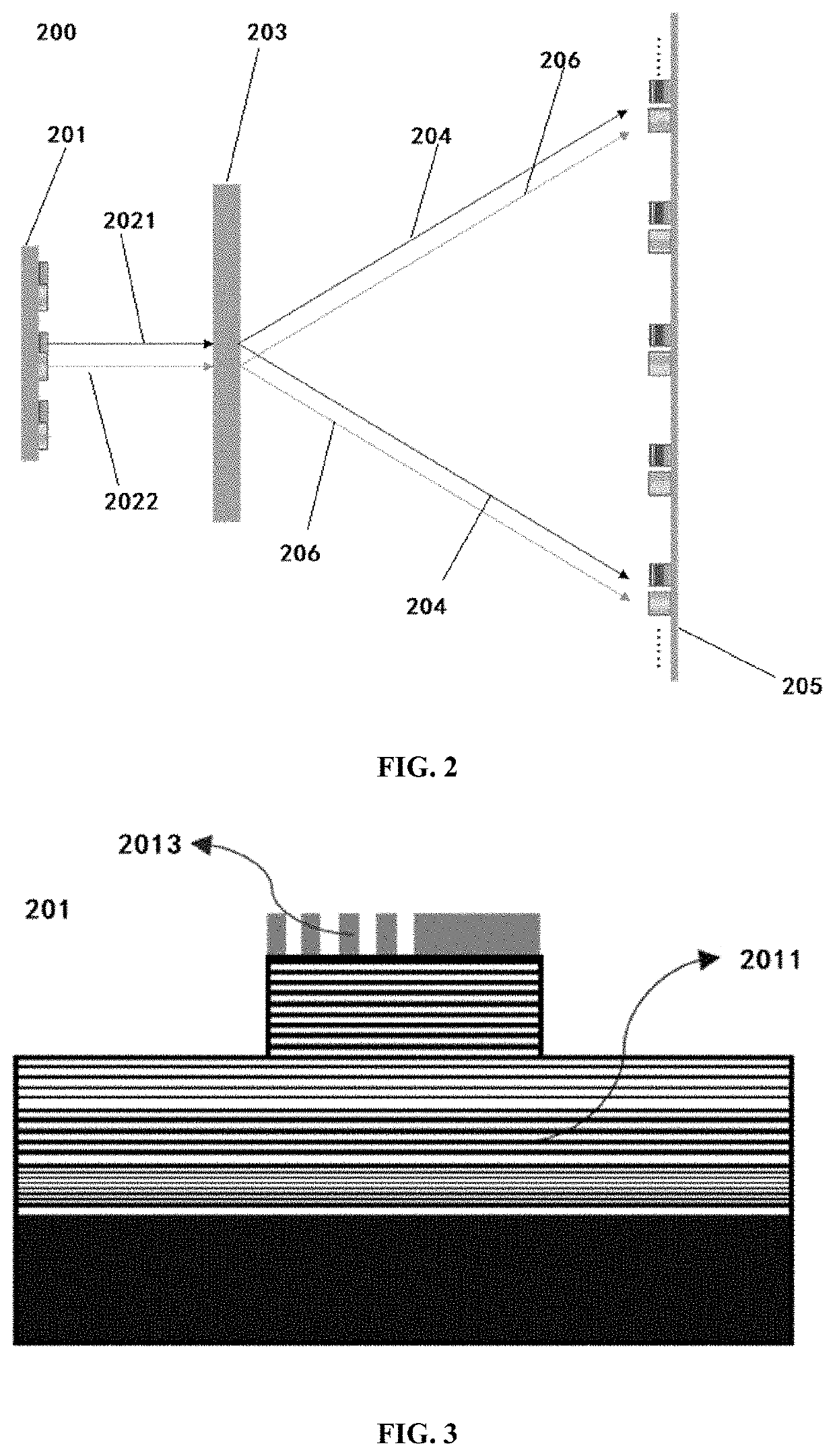
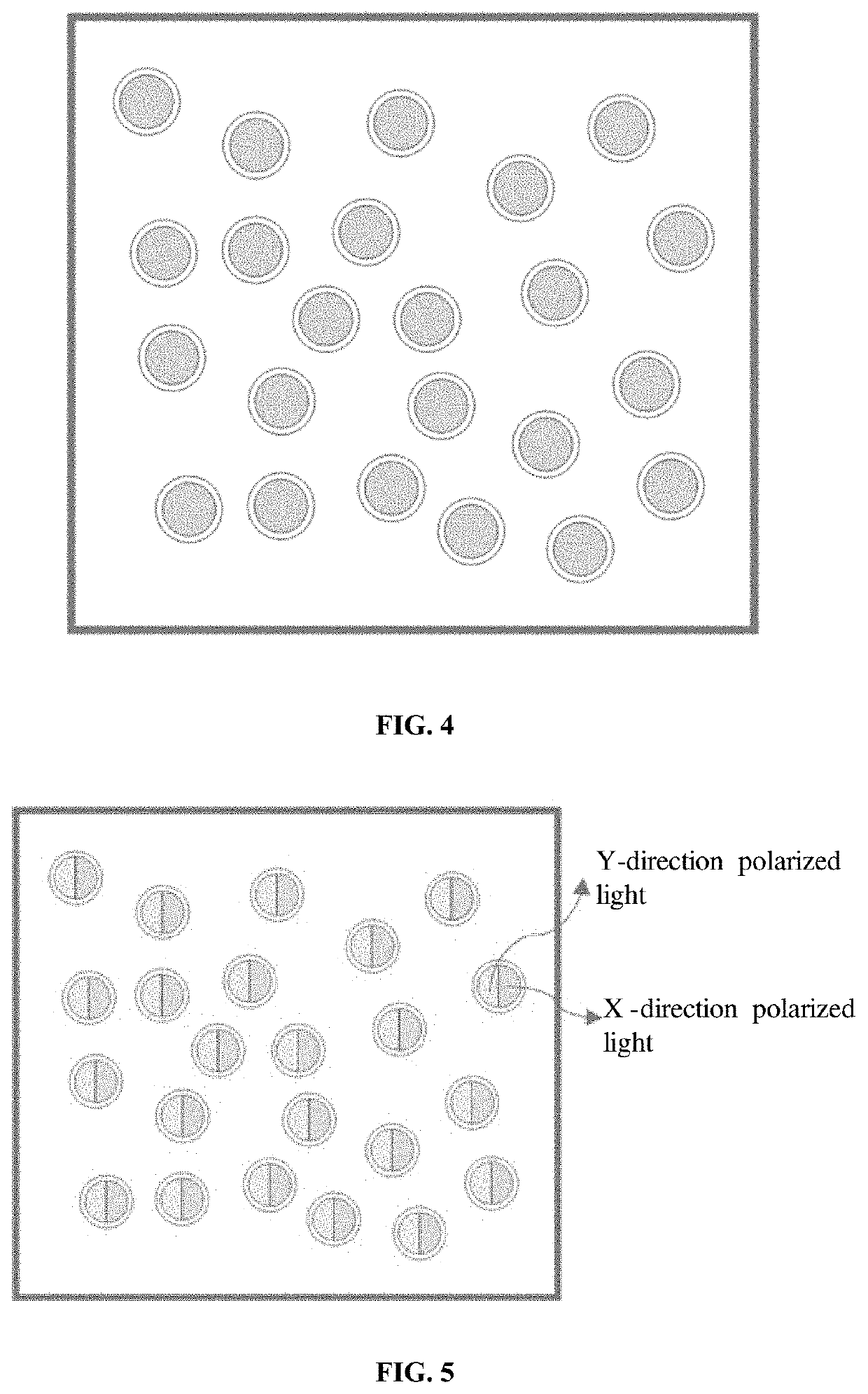
[0006]In accordance with one aspect of the present invention, a polarization modulation element is provided between the light-emitting device and the diffractive optical element, the polarization modulation element being configured to modulate light emitted from the light-emitting device into at least two groups of polarized light in different polarization directions, the number of groups of which corresponds to that of the at least two groups of light beams, and the diffractive optical element being configured to modulate the at least two groups of polarized light so as to project the at least two groups of light beams, wherein the polarization modulation element is preferably a polarization grating and/or a polarizing film, and the light-emitting device is preferably a vertical cavity surface emitting laser or an edge emitting laser or an LED. In the examples of the

Problems solved by technology

Now the main structural component DOE of a structured light projection module is limited by the manufacturing capacity, therefore the minimum characteristic size cannot be further reduced, resulting i

Method used


Image

  • Beam-splitting optical module and manufacturing method thereof
  • Beam-splitting optical module and manufacturing method thereof
  • Beam-splitting optical module and manufacturing method thereof

Examples


Example

[0035]Certain exemplary examples will be described below only in a brief manner. Just as those skilled in the art will appreciate, changes in various ways to the examples described herein can be carried out without departing from the spirit or scope of the present invention. Therefore, the drawings and the following description are deemed essentially exemplary, instead of limitative.

[0036]In the description of the present invention, it needs to be understood that the orientation or position relations denoted by such terms as “central”“longitudinal”“latitudinal”“length”“width”“thickness”“above”“below”“front”“rear”“left”“right”“vertical”“horizontal”“top”“bottom”“inside”“outside”“clockwise”“counterclockwise” and the like are based on the orientation or position as shown in the accompanying drawings, and are used only for the purpose of facilitating description of the present invention and simplification of the description, instead of indicating or suggesting that the denoted devices or...


PUM


Abstract

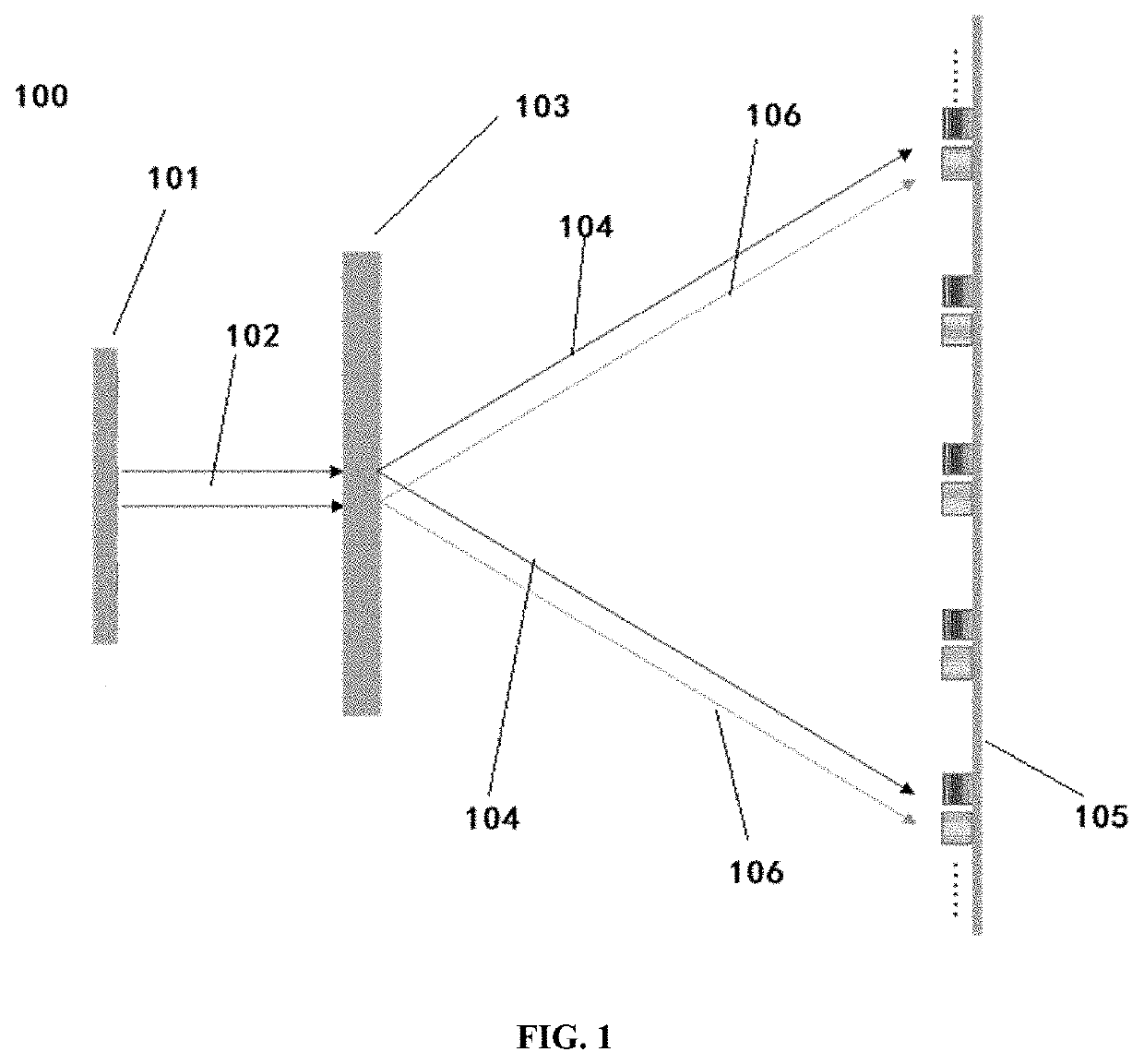
A beam-splitting optical module (100), comprising: a light-emitting device (101); and a diffractive optical element (103), wherein the diffractive optical element (103) is provided in a light exit path of the light-emitting device (101), and is configured to modulate incident light to project at least two groups of light beams, and can form, on a target surface (105), at least two groups of light spots, the number of groups of which corresponds to that of the light beams, wherein polarization directions of at least two groups of light beams are different, and/or optical distances from the light-emitting device (101) to the target surface (105) are different.

Description

TECHNICAL FIELD[0001]The present invention relates to the technical field of optics, especially to the technical field of the modulation and projection of a diffractive optical element.BACKGROUND[0002]At present, mobile phone manufacturers gradually begin to adopt the structured light three-dimensional sensing technology. The structured light is an active triangulation technology, and the basic principle of the same lies in using a laser projector to project controllable photoelectricity, optical strip or optical surface onto the surface of an object to form a feature point, using a camera to take an image to obtain a projection angle of the feature point, then calculating the distance between the feature point and the main point of the camera lens according to the calibrated space direction and position parameters under the triangulation principle, and obtaining a 3D shape of the sensed object so as to complete facial recognition, 3D modeling, etc. Currently, the common structured ...

Claims


Application Information

Patent Timeline
IPC IPC(8): G02B27/42G02B27/10G02B27/28
CPCG02B27/4233G02B27/283G02B27/1086G02B27/144G02B27/18
Inventor LUO, QUNYANG, XINGPENGYUAN, MING
Owner HANGZHOU YUGUANG OPTOELECTRONICS TECH CO LTD
Why Eureka
Try Eureka