
Antenna structure

a technology of antenna array and antenna body, applied in the field of antenna structure, can solve the problem of limited performance of antenna array, and achieve the effect of high transmission and reception performan

Active Publication Date: 2022-03-10
HTC CORP
View PDF1 Cites 0 Cited by
  • Summary
  • Abstract
  • Description
  • Claims
  • Application Information

AI Technical Summary

Benefits of technology

[0004]The objective of the invention is to provide an antenna structure that has radiation pattern switching functions of switching its radiation pattern based on its surrounding environment, thus achieving high transmission and reception performances under various environments.

Problems solved by technology

Further, the conventional antenna does not have radiation pattern switching functions, and therefore its performance tends to be limited due to its surrounding environment.

Method used


Image

  • Antenna structure
  • Antenna structure
  • Antenna structure

Examples


Embodiment Construction

[0018]The spirit of the disclosure is clearly described hereinafter accompanying with the drawings and detailed descriptions. After realizing preferred embodiments of the disclosure, any persons having ordinary skill in the art may make various modifications and changes according to the techniques taught in the disclosure without departing from the spirit and scope of the disclosure.

[0019]Terms used herein are only used to describe the specific embodiments, which are not used to limit the claims appended herewith. Unless limited otherwise, the term “a,”“an,”“one” or “the” of the single form may also represent the plural form. Further, the spatially relative terms are intended to encompass different orientations of the device in use or operation in addition to the orientation depicted in the figures. The apparatus may be otherwise oriented (rotated 90 degrees or at other orientations) and the spatially relative descriptors used herein may likewise be interpreted accordingly.

[0020]The...


PUM


Abstract

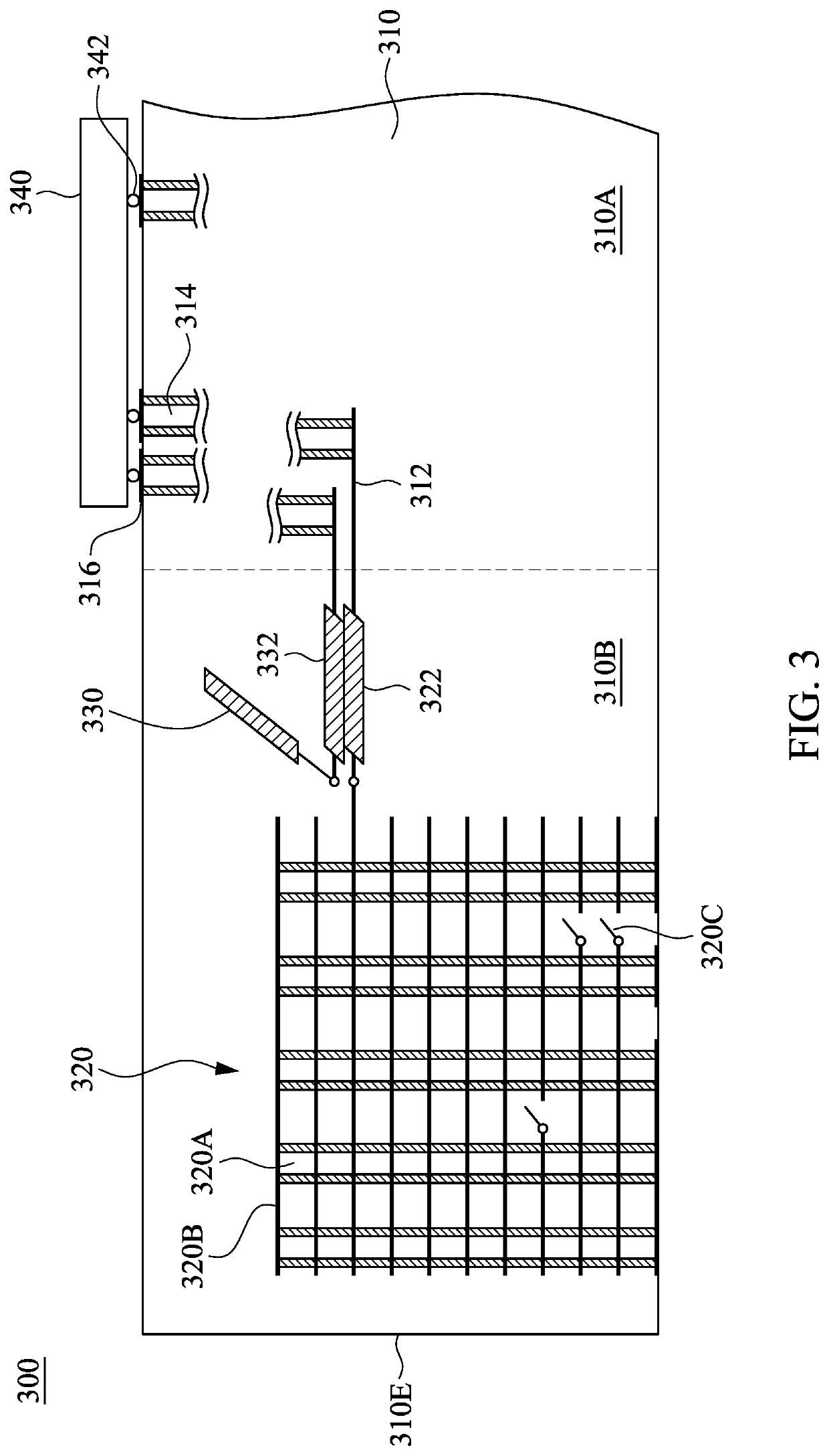
An antenna structure is provided, which includes a substrate, a horizontal radiator and a vertical radiator. The horizontal radiator is on or in the substrate. The vertical radiator is in the substrate and includes a vertical conductor, planar metal structures and a switch. The planar metal structures are electrically connected through the vertical conductor. The switch is in a gap of the planar metal structures and is coupled to at least one of the planar metal structures for switching a current distribution of the vertical radiator.

Description

RELATED APPLICATIONS[0001]This application is a continuation application of U.S. application Ser. No. 16 / 219,918, filed Dec. 13, 2018, which is incorporated herein by reference in its entirety.BACKGROUNDTechnical Field[0002]The invention relates to an antenna structure, and more particularly to an antenna structure that is capable of switching its radiation pattern.Description of Related Art[0003]With the vigorous development of communication technologies, commercial mobile communication systems can achieve high-speed data transmission, and provide Internet service providers with a wide range of services, such as network services of multimedia video streaming, instant road reporting and navigation, and instant network communication that require huge data transmission quantity. For hardware, an antenna design affects the performance of the wireless signals transmitting and receiving. Further, the conventional antenna does not have radiation pattern switching functions, and therefore ...

Claims


Application Information

Patent Timeline
Patent Type & Authority Applications(United States)
IPC IPC(8): H01Q3/24H01Q9/04H01Q21/06
CPCH01Q3/24H01Q21/064H01Q9/0407H01Q1/36H01Q1/50H01Q1/2283H01Q21/245
Inventor PU, TA-CHUNHO, CHIEN-TINGKUO, YEN-LIANG
Owner HTC CORP
Learn More