Ultrasonic wave propagation time measuring system

a propagation time and ultrasonic wave technology, applied in the field of position detection methods, can solve the problems of difficult implementation in a small-sized movable object such as an electronic pen or the like, difficult to use various types of modulation methods, and low transmission gain at other frequencies, so as to achieve ultrasonic wave propagation time measurement compactly, high transmission and reception gain, good modulation characteristics

Active Publication Date: 2012-10-02
NEC CORP
View PDF10 Cites 2 Cited by
  • Summary
  • Abstract
  • Description
  • Claims
  • Application Information

AI Technical Summary

Benefits of technology

[0036]As described above, by selecting a piezoelectric transducer element having a high transmission and reception gain, in a higher frequency range, for example, in a frequency range 1.5 times or especially 2N times a frequency of an M-sequence modulation model wave, it is possible to narrow the band of an ultrasonic wave transmission wave with a good modulation characteristic, and a...

Problems solved by technology

As a means of generating a signal in this frequency range with sufficient sound pressure, a so-called speaker, which electromagnetically vibrates a small-sized diaphragm of high rigidity, is known, but since miniaturization is difficult and since power consumption is large due to electrical current driving, implementation in a small-sized movable object such as an electronic pen or the like is difficult.
However, in a case of using a resonance ph...

Method used


Image

  • Ultrasonic wave propagation time measuring system
  • Ultrasonic wave propagation time measuring system
  • Ultrasonic wave propagation time measuring system

Examples


Embodiment Construction

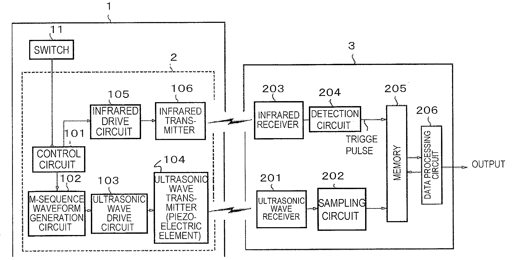
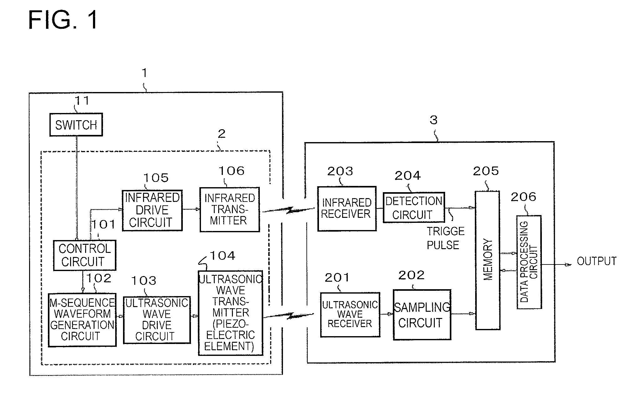
[0055]Next, a detailed description of a preferred embodiment for implementing the present invention is given, taking an electronic pen system as an example and making reference to FIGS. 1 to 7. In a robot system, by installing an ultrasonic wave transmission unit at an obstruction and installing a reception unit in a robot, the present invention enables evasive action control by computing distance to the obstruction, and in a medical care system, by having a patient wear an ultrasonic wave transmission unit, the invention enables identifying the location of the patient.

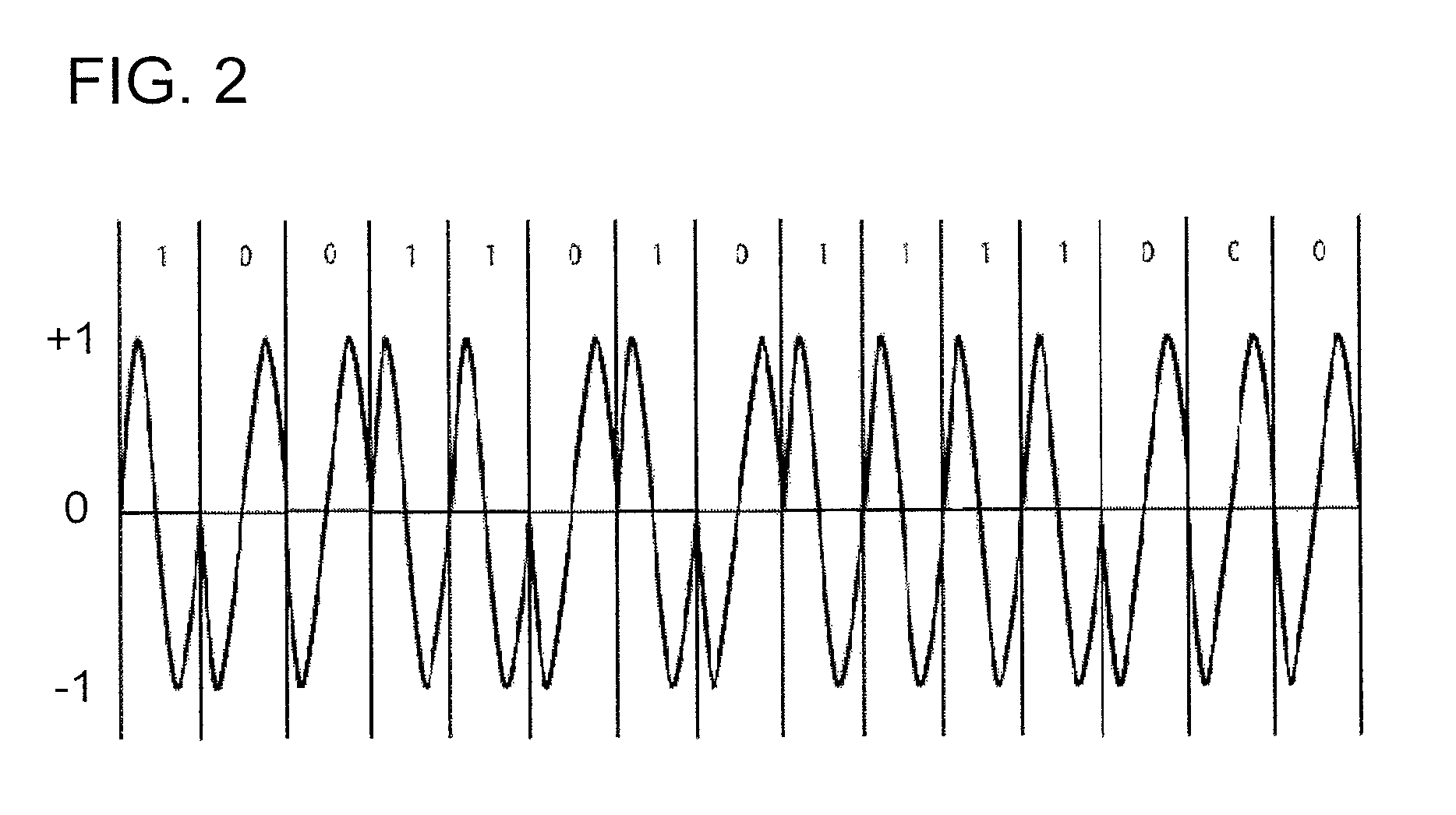
[0056]Furthermore, an ultrasonic wave modulation method presents cases of performing phase modulation using an M-sequence signal of a pseudo-random signal with high autocorrelativity, but a similar effect can be anticipated with other modulation methods. In addition, a signal sequence that is the basis of modulation may be a pseudo-random signal, having a signal sequence with high autocorrelativity, and a similar effe...


PUM


Abstract

A position detection method and system that eliminate an effect of residual vibration of a piezoelectric or magnetostrictive element, increase correlativity between a received ultrasonic waveform and a model waveform, and are not affected by a reflected wave of an ultrasonic wave signal. A transmission unit of an ultrasonic wave propagation time measuring system of the present invention generates an electromagnetic wave signal including a trigger signal that indicates transmission timing and an ultrasonic wave drive signal by modulating an ultrasonic wave on the basis of a pseudo-random signal with high autocorrelativity at the same time as transmission of the electromagnetic wave signal, and transmits an ultrasonic wave signal of a frequency higher than a frequency of the ultrasonic wave drive signal by an ultrasonic wave transmitter. A reception unit detects the electromagnetic wave signal and the ultrasonic wave signal, and is provided with a data processing circuit for computing, with the ultrasonic wave drive signal as a model waveform, correlation values between the detected ultrasonic wave signal and the model waveform, detecting a main peak value of the computed correlation values, and computing an ultrasonic wave propagation time from a point in time of detection of the electromagnetic wave signal and a point in time of detection of the main peak value.

Description

RELATED APPLICATION[0001]This application is based upon and claims the benefit of the priority of Japanese Patent Application No. 2007-224859 (filed on Aug. 30, 2007) and also Japanese Patent Application No. 2008-159151 (filed on Jun. 18, 2008), the disclosure of which is incorporated herein in its entirety by reference thereto.[0002]The present invention relates to a method of measuring propagation time of an ultrasonic wave from an ultrasonic wave generation source as far as a prescribed position, and to an ultrasonic wave propagation time measuring system.TECHNICAL FIELDBackground Art[0003]As one example of a conventional position detection method using an ultrasonic wave, an electronic pen system is disclosed in Patent Document 1. This position detection system is formed of an electronic pen that has a function of transmitting an ultrasonic wave signal of a fixed waveform at a fixed period and an infrared trigger signal at a fixed period, and a reception unit for receiving the t...

Claims


Application Information

Patent Timeline
IPC IPC(8): G01S15/00
CPCG06F3/0433G01S11/16
Inventor KAJITANI, HIROSHIMIYAMOTO, JUNICHI
Owner NEC CORP
Why Eureka
Try Eureka