
Waveguide image combiners for augmented reality displays

Pending Publication Date: 2020-10-29
A9 COM INC
View PDF2 Cites 3 Cited by
  • Summary
  • Abstract
  • Description
  • Claims
  • Application Information

AI Technical Summary

Benefits of technology

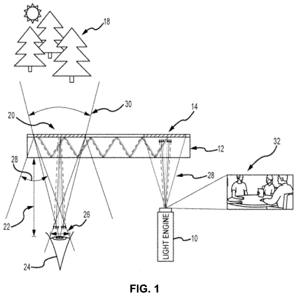
The present invention is a waveguide image combiner that allows for the transmission of monochrome or full-color images in an augmented reality display. The combiner has a large horizontal and vertical field of view (FOV) and high light efficiency. It uses reflection volume holographic optical elements (VHOEs) that have a relatively high outcoupling efficiency and can outperform surface relief gratings. Additionally, a Y expander is used to improve the overall light transmission through the system by expanding the vertical FOV. The Y expander provides transmission efficiencies of >80% and is compatible with the single-film incoupling and outooupling VHOE design.

Problems solved by technology

Current embodiments have diagonal FOVs that are less than 40 degrees and eye boxes of less than 10 mm×10 mm, which negatively impacts the user's experience.
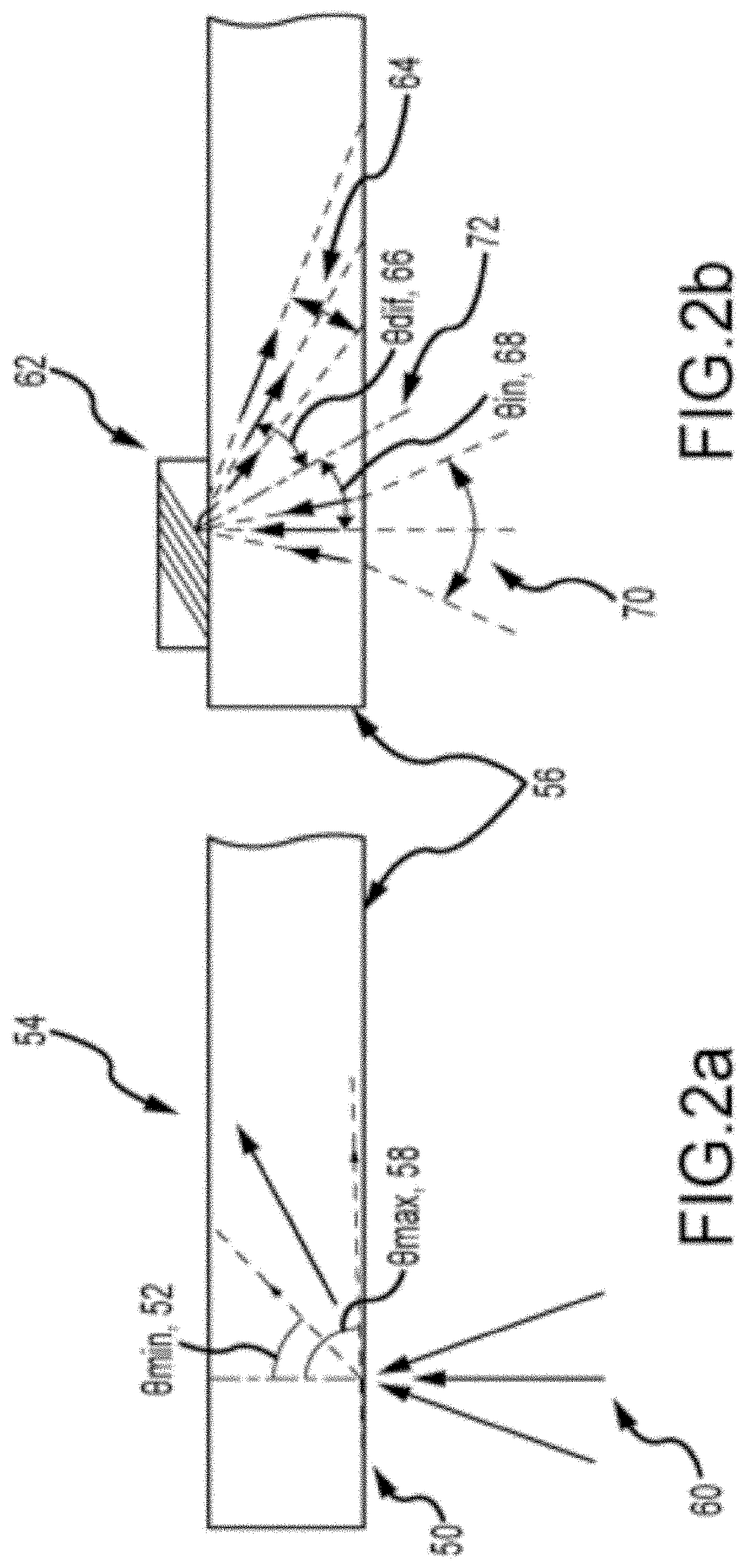
However, a reflection VHOE recorded in a single layer has an acceptance angle of less than 5° because of the high angular selectivity of volumetric holograms (low diffraction efficiency outside 5 degrees).
While expanding the FOV for narrowband laser-based systems using HOEs with optical power is possible, the resulting small eye-box size (˜5 mm), laser speckle, and eye safety concerns, make this approach impractical.
1) and their use for imaging with broadband sources leads to chromatic aberrations.
However, recording materials with exceptionally high Δn reported in the literature, are not well suited for WG applications because of their high absorption and scattering affects.
Consequently, multiple bounces result in the expansion of the horizontal FOV.
They also don't allow for red green and blue light to be incoupled using one layer because of color separation and need at least two layers separated by an air gap to produce a full-color image.

Method used


Image

  • Waveguide image combiners for augmented reality displays
  • Waveguide image combiners for augmented reality displays
  • Waveguide image combiners for augmented reality displays

Examples


example

[0137]The following is a non-limiting example of the present invention. It is to be understood that said example is not intended to limit the present invention in any way. Equivalents or substitutes are within the scope of the present invention.

[0138]The following is a non-limiting example of the present invention. It is to be understood that said example is not intended to limit the present invention in any way. Equivalents or substitutes are within the scope of the present invention.

[0139]A method of near-to-eye display (NED) is presented that uses an in-line surface-relief grating (SRG) attached to a waveguide propagation NED to achieve a large field of view without the need for large projection optics. Horizontal pupil expansion is achieved using an extraction hologram that is multiple times the size of the injection hologram and is recorded with modulated diffraction efficiency. Vertical pupil expansion is achieved by coupling the SRG to the waveguide surface between the inject...


PUM


Abstract

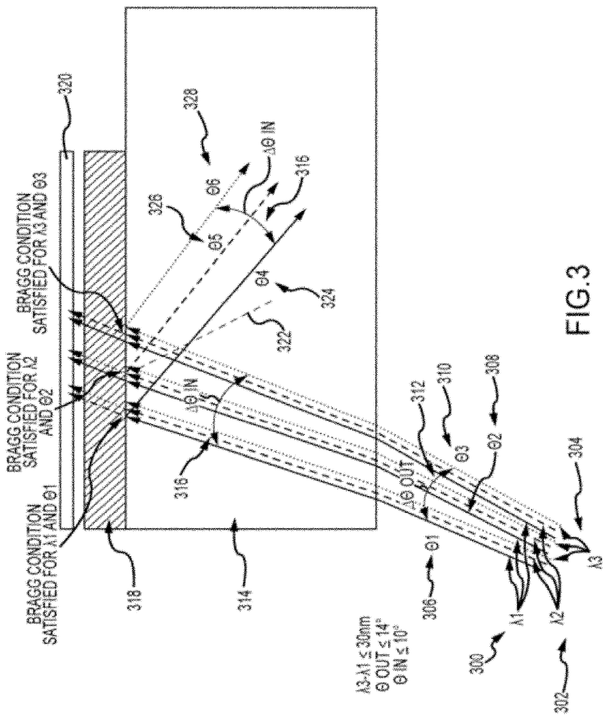
A waveguide image combiner is used to transmit a monochrome or full-color image in an augmented reality display. The combiner uses multiple stacked substrates and multiple pairs of incoupling and outcouping VHOEs to expand a first FOV and an image expander to expand the second or perpendicular FOV. This suitably provides an expanded FOV that offers a diagonal FOV≥50°, a horizontal FOV≥40 and a vertical FOV≥25°. The combiner also delivers a large horizontal eye box up to 20 mm and a vertical eye box of 10 mm while maintaining high light efficiency of the real scene (e.g. >80%). The system is able to use a light engine based on broadband (10 nm≤Δλ≤40 nm) LEDs and maintain a large horizontal field of view and high transmission of the real imagery. The approach resolves issues with current embodiments including astigmatism, image overlap, color balance, and small light engine pupils leading to reduced eye boxes.

Description

CROSS-REFERENCES TO RELATED APPLICATIONS[0001]This application is a continuation-in-part, and claims benefit of U.S. patent application Ser. No. 16 / 832,611, filed Mar. 27, 2020, which is a continuation-in-part of U.S. patent application Ser. No. 16 / 041,347, filed Jul. 20, 2018, which is a non-provisional of U.S. Provisional Application No. 62 / 547,411, filed Aug. 18, 2017, the specifications of which are incorporated herein in their entirety by reference.BACKGROUND OF THE INVENTIONField of the Invention[0002]This invention relates to waveguide image combiners for combining real imagery and auxiliary content to generate an augmented reality display.Background Art[0003]Combining computer-generated imagery with real imagery exists in a continuous range described as the reality-virtuality continuum. At one end of the continuum exists “reality”, the image reaching the viewers eye has no computer generated information. At the other end is “virtual reality” where all the information reachin...

Claims


Application Information

Patent Timeline
IPC IPC(8): G02B27/01F21V8/00G02B5/32
CPCG02B5/32G02B2027/0123G02B6/005G02B27/0172G02B6/0026G02B2027/0174G02B6/0016G02B6/0043G02B27/0081G02B2027/0178G02B2027/0125
Inventor BABLUMYAN, ARKADYFARD, ERFAN
Owner A9 COM INC
Learn More