
Liquid Crystals Composition and Liquid Crystal Display with Patterned Electrodes

a technology of liquid crystals and electrodes, applied in the field of liquid crystal composition, can solve the problems of damage to alignment films, fine pixel electrodes, and increased costs associated with fine dust and fine electric discharge, and achieve stable polymer stability, high optical performance, and high light efficiency

Inactive Publication Date: 2011-03-31
UNIV OF CENT FLORIDA RES FOUND INC +1
View PDF2 Cites 43 Cited by
  • Summary
  • Abstract
  • Description
  • Claims
  • Application Information

AI Technical Summary

Benefits of technology

[0013]A fourth objective of the invention is to provide new methods, systems and devices for a blue phase liquid crystal display device that could have a high light efficiency.
[0014]The present invention produces a stable polymer stabilized blue phase liquid crystal. By proper use of the present invention shows clearing point temperature of the polymer-LC composite increased to 100° C. and above. Utilizing high optical and high dielectric anisotropy liquid crystals, the co-inventors have obtained compositions with extraordinarily high optical anisotropy and at the same time high dielectric anisotropy. Having both properties at the high level leads to a possibility of reduced thickness of an electro-optical cell of a display and lower threshold and operating voltage compared with common liquid crystal materials used prior to this invention.
[0015]An embodiment of the present invention provides a blue phase liquid crystal composition having a core group and at least one of a terminal group and a lateral group connected to the core group in a combination wherein the core group has a first end and a second end and forms a central axis and is selected from a cyclic group consisting of at least one of a phenyl group, a cyclohexyl group and a heterocyclic group; the terminal group attaches to the first end and the second end of the core group and is selected from a non-polar group consisting of at least one of an alkyl group, an alkoxy group, and an alkenyl group and a polar group selected from at least one of fluorine (F), chlorine (Cl), carbon nitride (CN), isothiocyanate (NCS), an alkoxyfluoroakyl radical (OCF2) and carbon trifluoride (CF3) to increase optical anisotrophy through elongated π-electron conjugation along the principal molecular axis; the lateral group is positioned between the first end and second end of the core group and is selected from a non-polar group consisting of at least one of an alkyl group, an alkoxy group, and an alkenyl group and a polar group selected from at least one of fluorine (F), chlorine (Cl), carbon nitride (CN), isothiocyanate (NCS), an alkoxyfluoroakyl radical (OCF2) and carbon trifluoride (CF3) to increase melting point temperatures of the liquid crystal composition; and the resulting liquid crystal composition exhibits high optical and dielectric anisotropies with operational temperatures in a range between approximately −40° C. and approximately 106° C., low threshold and operating voltage, and light efficiency in liquid crystal display applications.

Problems solved by technology

The rubbing treatment is an operation in which a cloth or the like is used to rub an alignment film that has been surface coated onto a substrate surface and is in contact with liquid crystals, and is the cause of increased costs associated with fine dust and fine electric discharge which occurs due to high voltage static electricity.
The dusts cause a problem in highly fine pixel electrodes and thin-film transistors forming process in which film deposition, exposure, etching are repeated.
The local electric discharge would damage the alignment film, or cause disconnection or electrostatic discharge damage in thin-film transistors and transparent electrode such as ITO.
The existance of fine dust particles or fine electric discharge will result in declining yields and poorer display qualities.
In addition, all of the modes described above use nematic liquid crystals, and their response times are about several milliseconds at the shortest, thus limiting their application in dynamic picture displays used for television.
However, a relatively low clearing point temperature limits application potential of currently existing polymer-stabilized blue phase liquid crystal composites, because the thermal effect from backlight could heat up the liquid crystal to its isotropic state so that the device cannot respond to the electric field.

Method used


Image

  • Liquid Crystals Composition and Liquid Crystal Display with Patterned Electrodes
  • Liquid Crystals Composition and Liquid Crystal Display with Patterned Electrodes
  • Liquid Crystals Composition and Liquid Crystal Display with Patterned Electrodes

Examples


Embodiment Construction

[0072]Before explaining the disclosed embodiments of the present invention in detail it is to be understood that the invention is not limited in its application to the details of the particular arrangements shown since the invention is capable of other embodiments. Also, the terminology used herein is for the purpose of description and not of limitation.

[0073]The following abbreviations and acronyms are listed below to facilitate the explanation of the description of the present invention.

[0074]BPLCD is used herein to mean “blue phase liquid crystal display

[0075]CB15 is a chiral dopant material, S-4′-(2-methylbutyl)-4-cyanobiphenyl, commercially available from Merck & Co., Inc.

[0076]CF3 is the chemical symbol for “carbon trifluoride

[0077]Cl is the chemical symbol for “chlorine

[0078]CN is used herein to represent the “cyano group”

[0079]Darocur 1173 is a liquid photoinitiator, 2-Hydroxy-2-methyl-1-phenyl-propan-1-one, commercially available from Ciba Specialty Chemicals, Inc. Daroc...


PUM

PropertyMeasurementUnit
temperaturesaaaaaaaaaa
heightaaaaaaaaaa

Abstract

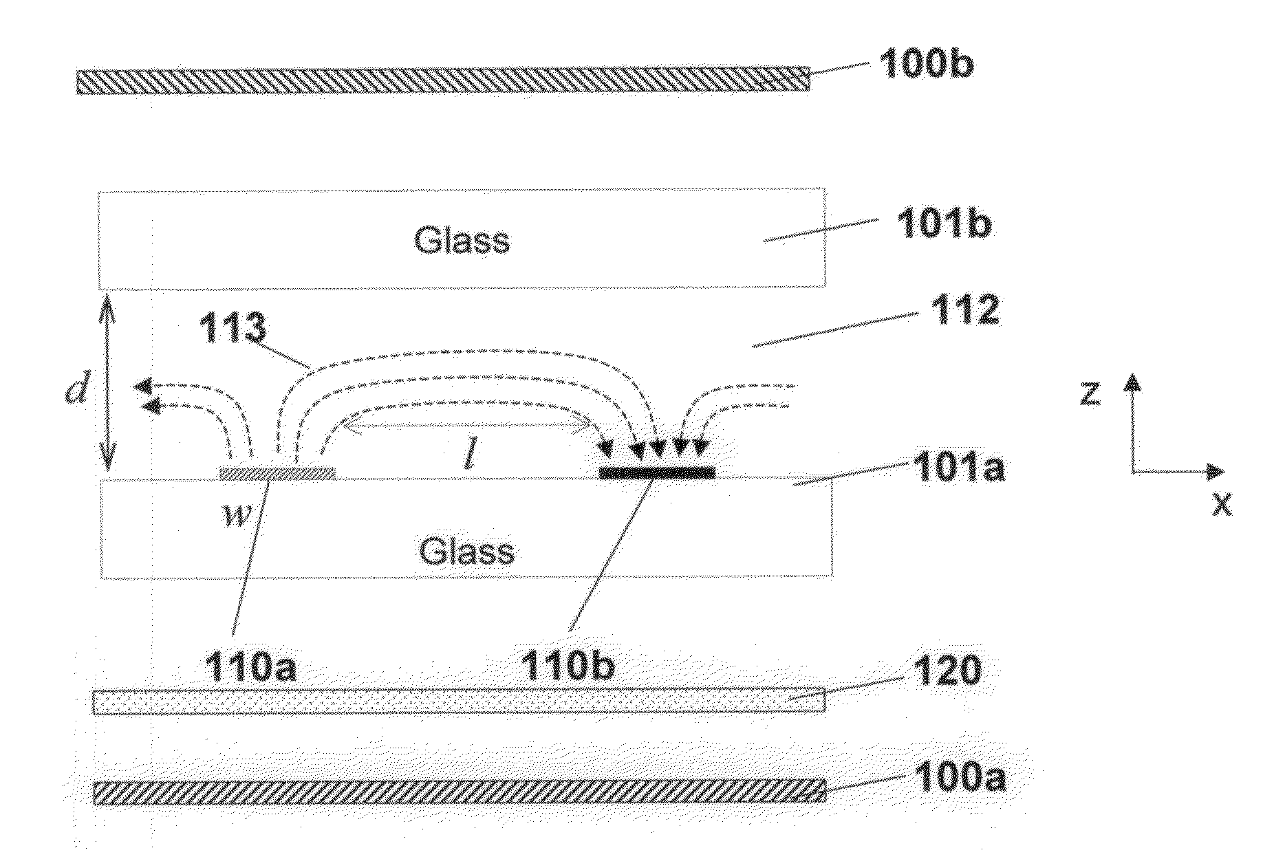
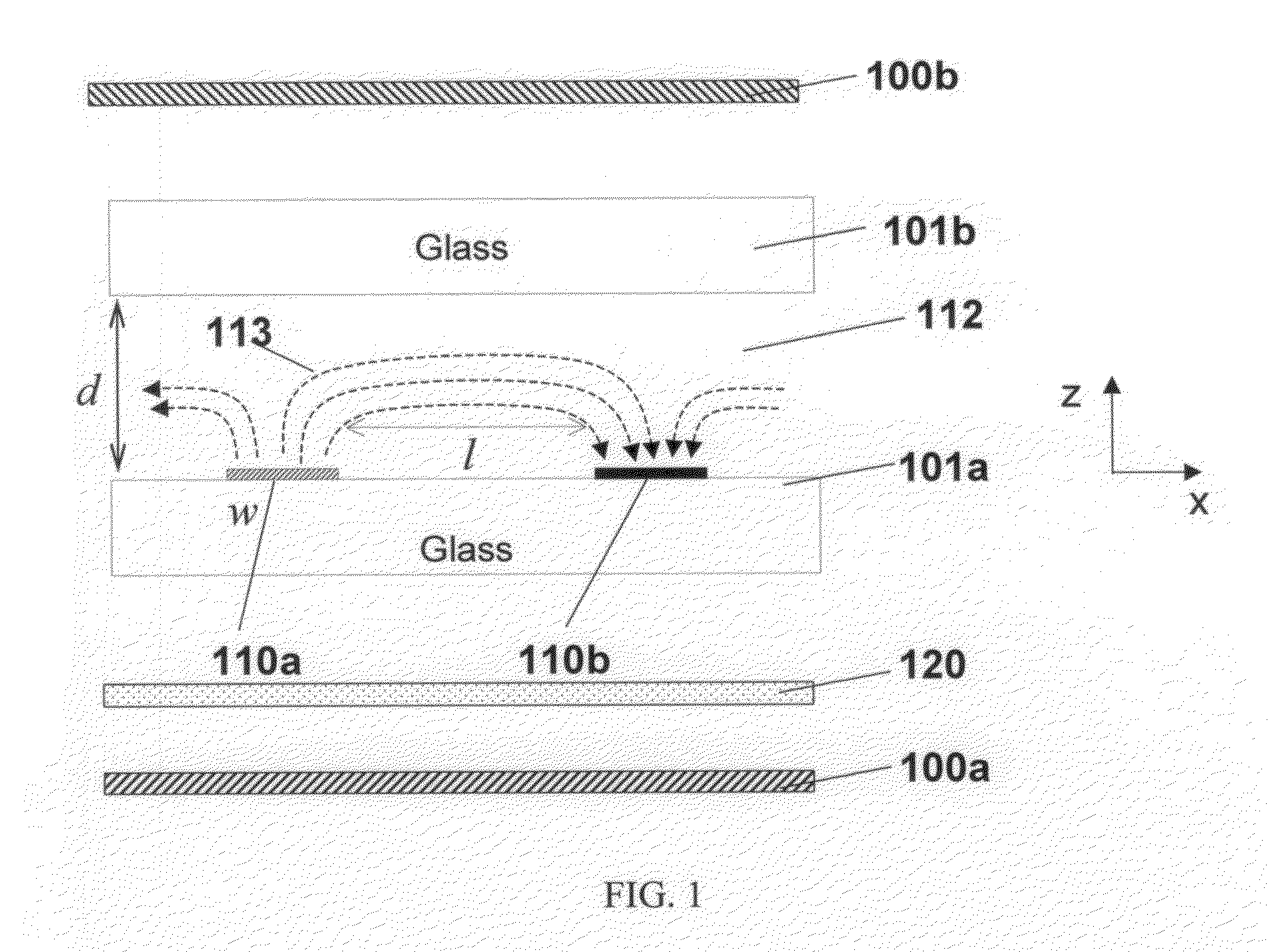
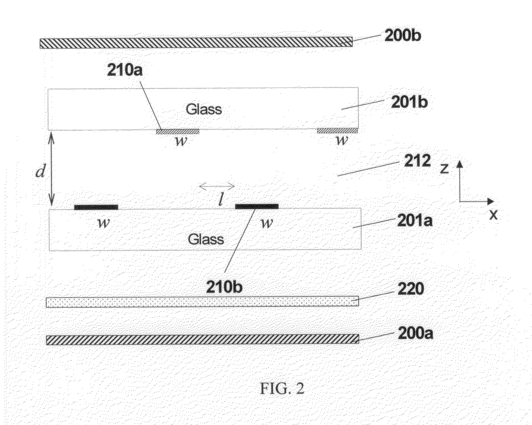
A blue phase liquid crystal composition and a LC display using the composition. The liquid crystal composition includes a first class including a highly polar compound and a second class including a highly conjugated liquid crystal compound. The blue phase liquid crystal display device includes first and second substrates each with polarizer on the exterior surface and the blue phase liquid crystal composition sandwiched therebetween with and patterned electrodes on one of the substrates or both substrates. The patterned electrodes can be T-shaped, chevron or v-shaped, thin comb like shape and can also be flat or trapezoidal. The device outputs different light transmissions from the electrically controllable induced birefringence of the blue phase LC material for a low driving voltage, high transmittance blue phase liquid crystal display device.

Description

[0001]This application claims the benefit of priority to U.S. Provisional patent application No. 61 / 246,718 filed on Sep. 29, 2009.FIELD OF THE INVENTION AND ART[0002]This invention relates to a liquid crystal composition and, in particular, to methods, systems and devices for a liquid crystal mixture that exhibits blue phase and is intended for a polymer stabilized composite and a liquid crystal display comprising the same.BACKGROUND OF THE INVENTION AND ART[0003]Liquid crystal display devices are widely used in the optical data processing field. The conventional liquid display modes include twister nematic, STN, in-plane switching, vertical alignment, multi-domain vertical alignment (MVA), OCB and the like. All of these modes cause the liquid crystal molecular orientation already under control to change into a different state of orientation when electrical fields are applied and change the polarization direction and polarization state of the transmitted light. The changes are conv...

Claims


Application Information

Patent Timeline
Patent Type & Authority Applications(United States)
IPC IPC(8): G02F1/1343G02F1/1335C09K19/32C09K19/30C09K19/34C09K19/20C09K19/02
CPCC09K19/0275Y10T428/10C09K19/322C09K19/3402C09K19/3483C09K19/404C09K19/46C09K19/586C09K2019/0496C09K2019/3422G02F1/133707G02F1/134363G02F2001/13793Y10T428/1036C09K19/2007
Inventor GAUZA, SEBASTIANWU, SHIN-TSONGE, ZHIBINGRAO, LINGHUIHSU, HSU-KUANCHIN, CHAO-LUNG
Owner UNIV OF CENT FLORIDA RES FOUND INC
Learn More