Ultrasonic Device And Ultrasonic Measuring Apparatus

a technology of ultrasonic measuring equipment and ultrasonic device, which is applied in the direction of mechanical vibration separation, wave based measurement system, instruments, etc., can solve the problems of reducing the transmission and reception accuracy the transmission sensitivity (acoustic pressure of the ultrasonic wave) of the ultrasonic wave decreases, and the ultrasonic wave is difficult to control transmission and reception. control, increase the transmitting and receiving sensitivity of the ultrasonic wave, suppress r

Active Publication Date: 2019-05-02
SEIKO EPSON CORP
View PDF0 Cites 1 Cited by
  • Summary
  • Abstract
  • Description
  • Claims
  • Application Information

AI Technical Summary

Benefits of technology

[0018]In the application example, as described above, in the ultrasonic device, the damper layer is provided, and thereby it is easy to control the transmission and reception of the ultrasonic wave. In addition, since the vibration of the vibration region is not inhibited by the damper layer, it is possible to increase the transmitting and receiving sensitivity of the ultrasonic wave, it is further possible to suppress the reverberant vibration, and it is possible to perform transmitting and receiving processes of the ultrasonic wave with high accuracy.
[0019]Hence, in the ultrasonic measuring apparatus, since the controller is capable of easily controlling the ultrasonic device and is capable of transmitting and receiving the ultrasonic wave with high transmission and reception accuracy, it is possible to measure the ultrasonic wave with high accuracy.

Problems solved by technology

However, when the diaphragm is solely configured to vibrate, a Q value of the diaphragm is increased, and thus it is difficult to control transmission and reception of the ultrasonic wave.
In addition, reverberant vibration (tailing of vibration) occurring after transmission of the ultrasonic wave is prolonged, and a problem arises in that transmission and reception accuracy of the ultrasonic wave decreases.
In this case, when an ultrasonic wave is transmitted, it is not possible to cause the vibration region to vibrate with a sufficient displacement, and thus transmitting sensitivity (acoustic pressure of the ultrasonic wave) of the ultrasonic wave decreases.

Method used


Image

  • Ultrasonic Device And Ultrasonic Measuring Apparatus
  • Ultrasonic Device And Ultrasonic Measuring Apparatus
  • Ultrasonic Device And Ultrasonic Measuring Apparatus

Examples


first embodiment

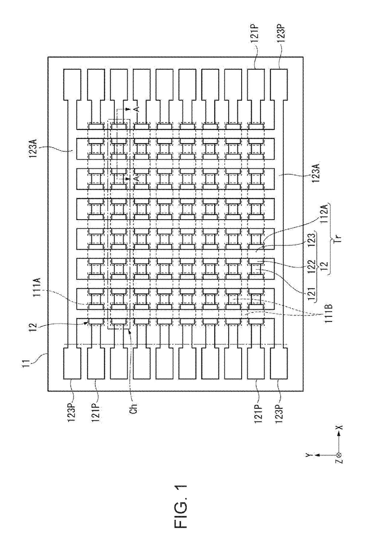
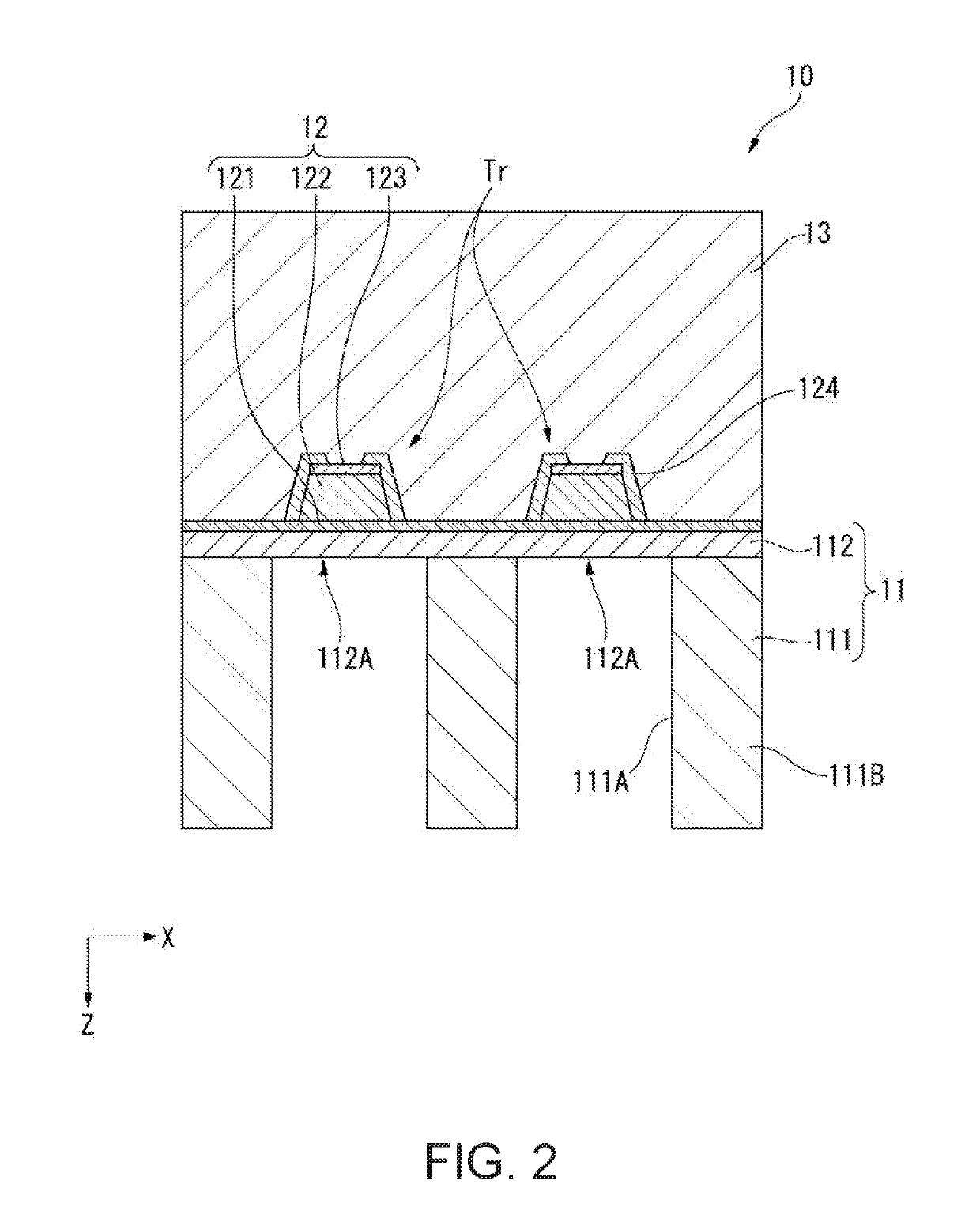
[0032]Hereinafter, an ultrasonic device according to a first embodiment of the invention will be described. FIG. 1 is a plan view illustrating a schematic configuration of an ultrasonic device 10. FIG. 2 is a sectional view of a part of the ultrasonic device 10 cut along line A-A in FIG. 1.

[0033]As illustrated in FIGS. 1 and 2, the ultrasonic device 10 is configured to include an element substrate 11, a piezoelectric element 12, and a damper layer 13 (refer to FIG. 2). Here, in the following description, a substrate thickness direction of the element substrate 11 is set as a Z direction, and two axial directions orthogonal to the Z direction is set as an X direction and a Y direction. In addition, the Z direction (direction toward a +Z side) corresponds to a first direction according to the invention and is a direction in which an ultrasonic wave is transmitted.

Configuration of Element Substrate 11

[0034]As illustrated in FIG. 2, the element substrate 11 includes a substrate main bod...

embodiment

Operational Effect of Embodiment

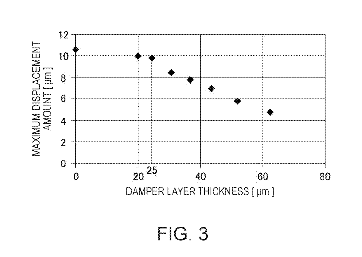
[0068]In the ultrasonic device 10 of the embodiment, the damper layer 13 is provided to be in contact with the vibration portion 112A on which the piezoelectric element is provided, the damper layer 13 has the thickness dimension of 13 μm or larger and 25 μm or smaller.

[0069]The damper layer 13 is provided. In this manner, it is possible to decrease the Q value of the vibration portion 112A, and it is possible to easily control the transmission and reception of the ultrasonic wave in the ultrasonic device 10. In other words, in a case where the damper layer 13 is not provided on the vibration portion 112A, the ultrasonic transducers Tr have very high responsiveness. Therefore, even in a case where a slight disturbance vibration is input to the ultrasonic device 10, a problem arises in that the vibration portion 112A vibrates and a receiving signal is output. In this case, although the ultrasonic wave is not input, the receiving signal is likely to be ...

second embodiment

[0076]Next, a second embodiment will be described. In the second embodiment, a distance sensor is described as an example of an ultrasonic measuring apparatus including the ultrasonic device 10 described in the first embodiment.

[0077]FIG. 9 is a diagram illustrating a schematic configuration of the distance sensor 100 according to the second embodiment.

[0078]As illustrated in FIG. 9, a distance sensor 100 of the embodiment is configured to include the ultrasonic device 10 and a controller 20 that controls the ultrasonic device 10. The controller 20 is configured to include a drive circuit 30, which drives the ultrasonic device 10, and a calculating unit 40. In addition, the controller 20 may include a storage unit in which various types of data, various types of programs, or the like for controlling the distance sensor 100 are stored.

[0079]The drive circuit 30 is a driver circuit for controlling the drive of the ultrasonic device 10 and includes a reference potential circuit 31, a s...


PUM


Abstract

An ultrasonic device includes: a vibration film provided with a vibration region that is vibratable by a vibration element; and a damper layer that is provided to cover the vibration region of the vibration film. The damper layer has a thickness dimension of 13 μm or larger and 25 μm or smaller.

Description

BACKGROUND1. Technical Field[0001]The present invention relates to an ultrasonic device and an ultrasonic measuring apparatus.2. Related Art[0002]In the related art, there has been known an ultrasonic device that outputs an ultrasonic wave to a target object (for example, see JP-A-2010-183437). JP-A-2010-183437 discloses the ultrasonic device (ultrasonic sensor) that includes a diaphragm (film), which is formed by etching a part of a support layer, and a piezoelectric laminate obtained by laminating a lower electrode, a piezoelectric film, and an upper electrode on the diaphragm. In the ultrasonic device, a thin film made of a fluorocarbon is provided to cover a surface of the diaphragm on a side on which the piezoelectric laminate is provided.[0003]In the ultrasonic device, application of a voltage to the lower electrode and the upper electrode of the piezoelectric laminate causes the diaphragm to vibrate, and vibration of the diaphragm directly acts on the air and generates a comp...

Claims


Application Information

Patent Timeline
Patent Type & Authority Applications(United States)
IPC IPC(8): G01S7/521
CPCG01S7/521B06B1/0622H10N30/302
Inventor OSAWA, EIJI
Owner SEIKO EPSON CORP
Why Eureka
Try Eureka