
Bilateral abrasive disc pad

a technology of abrasive discs and abrasives, which is applied in the direction of flexible wheel parts, metal-working equipment, manufacturing tools, etc., can solve the problems of affecting the efficiency of the multi-stage grinding or polishing operation, and affecting the efficiency of the multi-stage grinding operation. , to achieve the effect of reducing runout and unwanted vibration, avoiding thread strippage, and easy unscrewing

Pending Publication Date: 2022-03-17
ÜÇER ZIMPARA TASI SAN VE TIC LTD STI
View PDF12 Cites 0 Cited by
  • Summary
  • Abstract
  • Description
  • Claims
  • Application Information

AI Technical Summary

Benefits of technology

The patent text describes an improved flap-type abrasive disc pad for grinding and polishing operations. The pad has a relatively greater thickness in the center and a mounting section that can be easily detached and re-attached to the grinder shaft. The pad has a relatively even wear of the abrasive flaps and reduced vibration and runout compared to conventional disc pads. The pad can also accommodate grinding and polishing operations requiring different abrasive flap arrangements. The technical effects of the invention include improved efficiency, reduced vibration and runout, and improved wear distribution.

Problems solved by technology

The continuous exchanging of different abrasive discs slows the grinding operation and impairs productivity.
However, while such double-sided disc pads have increased operational efficiency, the applicant has observed several shortcomings which compromise the performance of such disc pads.
Such unscrewing and re-screwing of the mounting nut protracts the time necessary for a multi-stage grinding or polishing operation.
Another shortcoming associated with such prior art disc pads is their tendency to develop runout or vibration as a result of uneven wear of the overlapping abrasive flaps.
The resulting vibration compromises the quality of the griding or polishing operation and accelerates the fatigue of the operator.
While both uneven flap wear and the resulting vibration may be ameliorated by grinding or polishing as a lower rotational speed, such a lower speed slows down the grinding or polishing operation.

Method used


Image

  • Bilateral abrasive disc pad
  • Bilateral abrasive disc pad
  • Bilateral abrasive disc pad

Examples


Embodiment Construction

[0015]The invention will now be described with reference to the accompanying drawings. However, the invention is not limited to the particular illustrated embodiments. To the contrary, the invention is limited only by the accompanying claims and their equivalents.

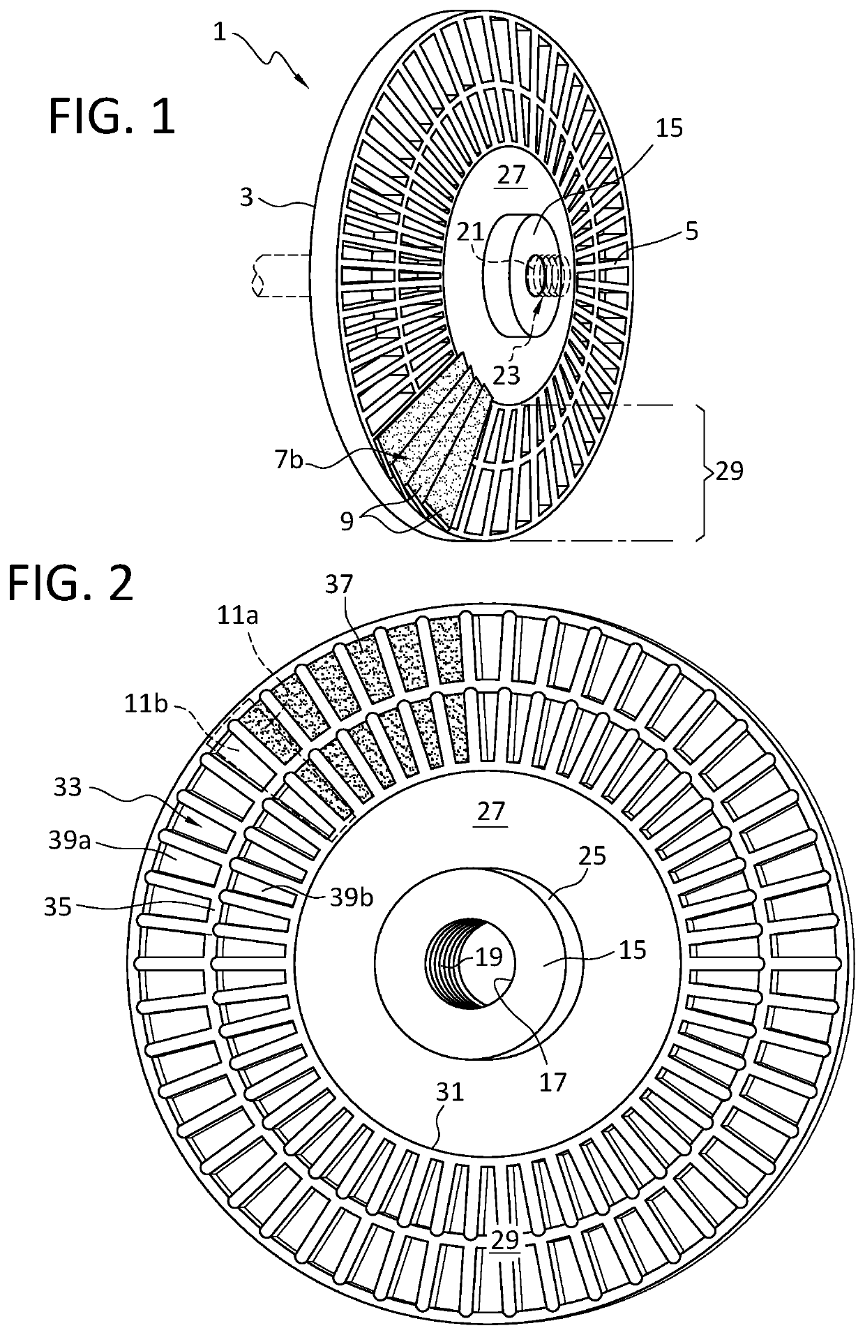
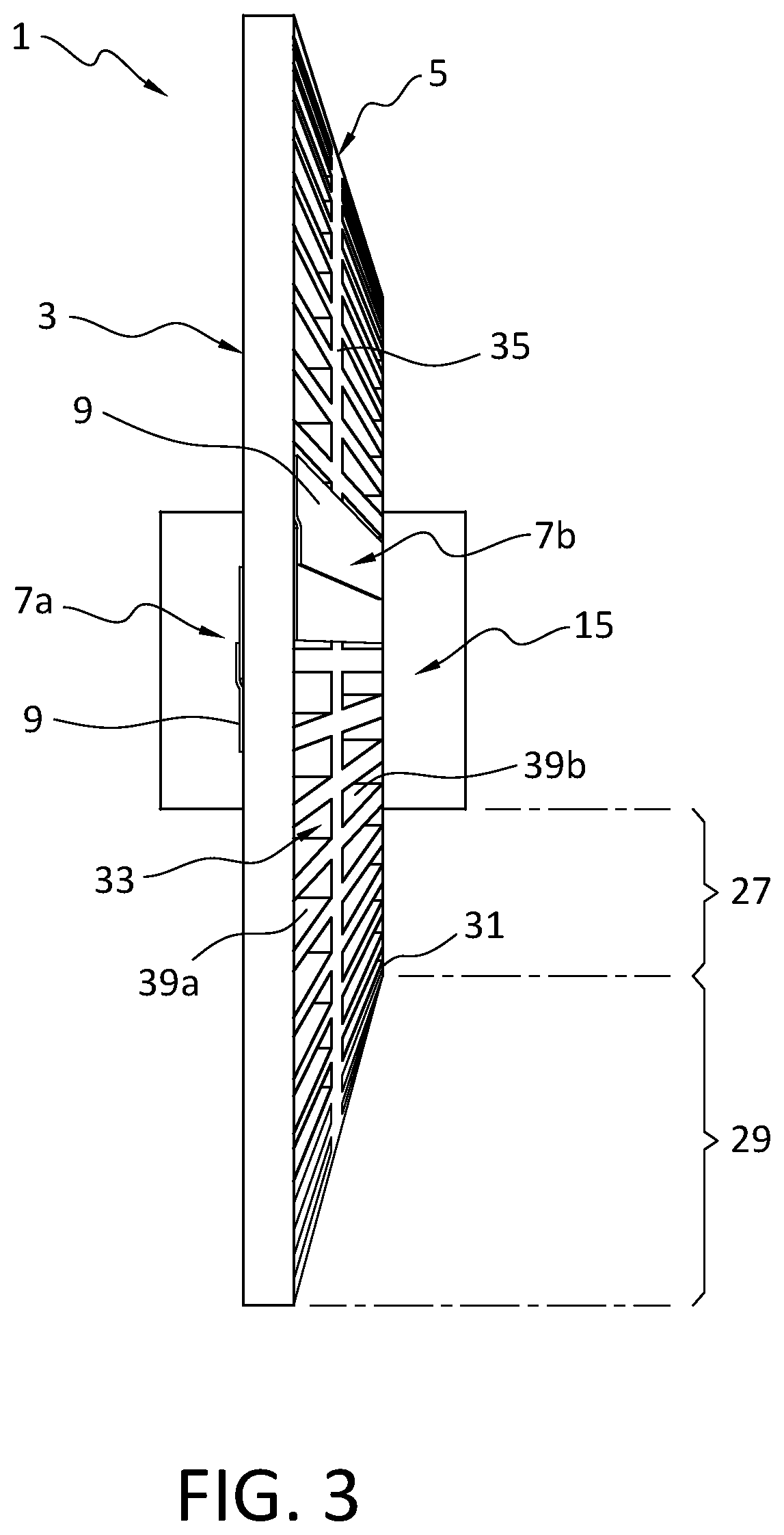
[0016]With reference to FIGS. 1-3, the double-sided abrasive pad 1 of the invention includes a flat side 3, a convex side 5, and two sets 7a, 7b of overlapping, fan-shaped adhesive flaps 9 mounted on the sides 3, 5 of the pad 1. Each of the flaps 9 has a bound side 11a affixed to the pad 1, and a free or loose side 11b that overlaps the bound side 11a of an adjacent flap 9. A cylindrically-shaped mounting section 15 forms the center section of the pad 1. The mounting section 15 has a mounting hole 17 concentrically positioned around the axis of rotation of the disc 1. The inner surface of the mounting hole 17 includes a screw thread 19 that is engageable with a complementary screw 21 thread of a driven shaft 23 of a grinder...


PUM


Abstract

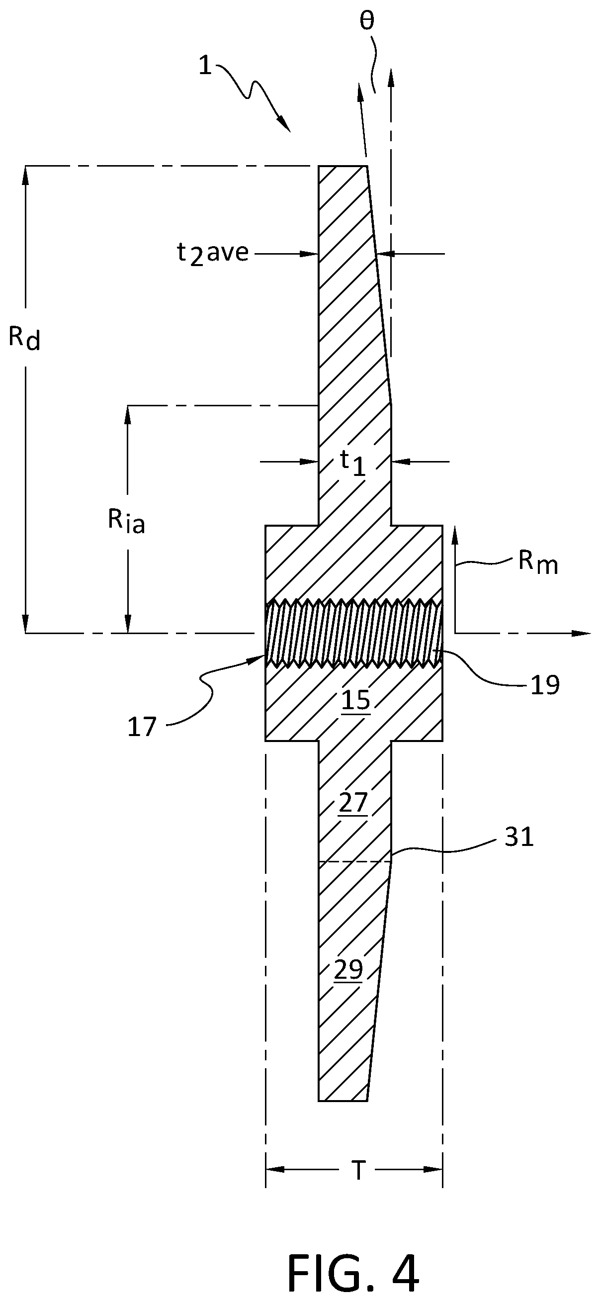
A bilateral abrasive disc pad is provided comprising a cylindrical mounting section, an inner annular section, and an outer annular section to which abrasive flaps are attached in an overlapping relationship. The cylindrical mounting section has a central screw-threaded mounting hole for threadedly connecting to a threaded driven shaft of a grinder. The outer annular section of one side is flat, while the outer annular section of the opposing side is convex. The cylindrical mounting section is substantially thicker than the outer annular section such that the ratio of the mass of the outer annular section to the mass of the combination of the cylindrical mounting section and the inner annular section is 2 to 1 or less. Such thickening of the central mounting section reduces runoff and vibration caused by uneven wear of the abrasive flaps and allows the pad to be securely attached to the shaft of the grinder without the need for a mounting nut.

Description

FIELD OF THE INVENTION[0001]The invention relates to a bilateral abrasive disc pad for grinding, polishing, and lustering a workpiece.BACKGROUND OF THE INVENTION[0002]Abrasives are used for polishing, cleaning, finalizing, and giving an aesthetic appearance to a workpiece. The smoother surfaces created by abrasives can also promote corrosion resistance and fracture resistance. Therefore, continuous improvements and innovations are made on abrasives.[0003]One type of abrasive disc pad known in the art as a flap-type disc comprises a disc-shaped pad onto which a plurality of overlapping abrasive flaps are glued or otherwise attached. In use, the flap-type disc is detachably mounted to the shaft of a hand grinder and the surface of a workpiece is abraded by the rotating abrasive flaps with the help of electrical power. While such flap-type abrasive discs have a more complex structure than simple abrasive discs that utilize only a single circular sheet of abrasive material, they have th...

Claims


Application Information

Patent Timeline
IPC IPC(8): B24D13/04B24D13/20
CPCB24D13/04B24D13/20B24D13/16
Inventor GÜÇTEKIN, AKIN
Owner ÜÇER ZIMPARA TASI SAN VE TIC LTD STI
Learn More