Printing apparatus, control method, and conveyance apparatus

a technology of printing apparatus and control method, applied in printing, other printing apparatus, etc., can solve the problems of deteriorating and achieve the effect of changing rigidity of print medium, appropriate suppression of deterioration in cutting accuracy of slitter

Pending Publication Date: 2022-03-17
CANON KK
View PDF1 Cites 0 Cited by
  • Summary
  • Abstract
  • Description
  • Claims
  • Application Information

AI Technical Summary

Benefits of technology

[0005]The present invention has been made in view of the above-described problems, so as to provide a technology capable of appropriately suppressing deterioration in cutting accuracy of a slitter although the rigidity of a print medium changes.

Problems solved by technology

Due to such a change in rigidity of the print medium, it becomes impossible to obtain the tension required to maintain preferable cutting accuracy, which causes the print medium to float or bend, and thus there has been a possibility that the cutting accuracy of the slitter is deteriorated.

Method used


Image

  • Printing apparatus, control method, and conveyance apparatus
  • Printing apparatus, control method, and conveyance apparatus
  • Printing apparatus, control method, and conveyance apparatus

Examples


first embodiment

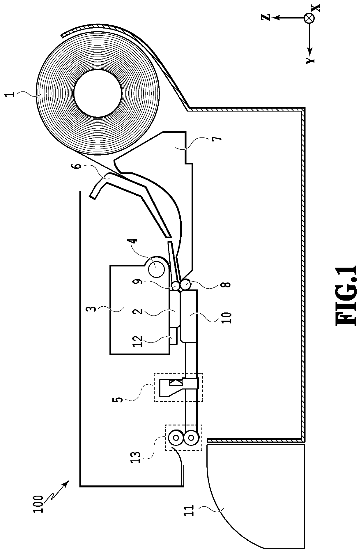
[0047]First, with reference to FIG. 1 through FIG. 13, an explanation will be given of a printing apparatus according to the first embodiment. FIG. 1 is a schematic configuration diagram of a printing apparatus according to an embodiment.

[0048]

[0049]The printing apparatus 100 of FIG. 1 is an inkjet printing apparatus that applies ink to a long sheet-shaped print medium for printing, based on job data which is output from a host apparatus (not illustrated in the drawings). In the present embodiment, the printing apparatus 100 holds a roll which is formed by winding the long sheet-shaped print medium 1. The print medium 1 unwound from the roll is conveyed downstream through a conveyance path formed by the upper guide 6 and the lower guide 7. Thereafter, the print medium 1 is nipped by the conveyance roller 8 and the pinch roller 9 and conveyed to an image printing part. The image printing part is equipped with the print head 2, the carriage 3 on which the print head 2 is mounted, and ...

second embodiment

[0139]Next, with reference to FIG. 14, FIG. 15A, and FIG. 15B, an explanation will be given of a printing apparatus according to the second embodiment. Note that, in the following explanation, the same or corresponding configurations as those of the first embodiment described above are assigned with the same reference signs as those used in the first embodiment, so as to omit the detailed explanations thereof.

[0140]The printing apparatus 100 according to the second embodiment is different from the above-described first embodiment in the aspects described below. That is, the ink application amount of an area in the vicinity of a cutting line to be cut by the slitter unit 303 in the print medium 1 including the cutting line is obtained, so that the conveyance amounts of the two conveyance rollers will be corrected according to the obtained ink application amount. In other words, in the present embodiment, the ink application amount of the cutting area in the image print area is obtain...

third embodiment

[0163]Next, with reference to FIG. 16, FIG. 17A, and FIG. 17B, an explanation will be given of a printing apparatus according to the third embodiment. Note that, in the following explanation, the same or corresponding configurations as those of the first embodiment described above are assigned with the same reference signs as those used in the first embodiment, so as to omit the detailed explanations thereof.

[0164]The printing apparatus 100 according to the third embodiment is different from the above-described first embodiment and second embodiment in the aspects described below. That is, as for a cutting area including a cutting line to be cut by the slitter unit 303 in the print medium 1, the ink application amount in each unit print area thereof is obtained, so that the conveyance by the conveyance mechanism in each unit print area is controlled according to the obtained ink application amount. In other words, in the present embodiment, the ink application amount of the cutting ...


PUM


Abstract

To provide a technology capable of appropriately suppressing deterioration in cutting accuracy of a slitter although the rigidity of a print medium changes, a printing apparatus is equipped with: a first conveyance unit configured to convey a print medium; a printing unit configured to print an image by applying ink to the print medium conveyed by the first conveyance unit; a cutting unit disposed on a downstream side in a conveyance direction in which the print medium is conveyed by the first conveyance unit and configured to cut the print medium, which is conveyed by the first conveyance unit, along the conveyance direction; and a second conveyance unit disposed on the cutting unit, and the printing apparatus includes a correction unit configured to correct a parameter related to conveyance of at least one of the first conveyance unit and the second conveyance unit, based on information about the print medium.

Description

BACKGROUND OF THE INVENTIONField of the Invention[0001]The present invention relates to a printing apparatus and conveyance apparatus that are capable of cutting a conveyed sheet-shaped print medium and a control method of the printing apparatus.Description of the Related Art[0002]Japanese Patent Laid-Open No. 2017-13438 discloses a technology related to a printing apparatus which is equipped with a slitter for cutting a printed print medium along the conveyance direction of the print medium. Specifically, according to the printing apparatus disclosed in Japanese Patent Laid-Open No. 2017-13438, the leading edge of a conveyed print medium is inserted to a blade part of the slitter, so that the print medium is cut along the conveyance direction in accordance with conveyance of the print medium.[0003]Further, the technology disclosed in Japanese Patent Laid-Open No. 2017-13438 has a configuration in which, of the rollers that convey the print medium, the rotation speed of the roller a...

Claims


Application Information

Patent Timeline
Patent Type & Authority Applications(United States)
IPC IPC(8): B41J11/66
CPCB41J11/663B41J11/009B41J11/706
Inventor KAWAFUJI, HIROSHITAIRA, HIROSHISATO, KAZUHIKOYOKOZAWA, TAKUKUNIMINE, NOBORUAICHI, AKIKOAZUMA, SATOSHIMOGI, SAEYOSHIZAWA, KEINISHIOKA, SHINGOSAITO, JUNICHINAGAI, HAJIMEBABA, NAOKOKONNO, YUJIYOSHIKAWA, SERENAWADA, SATOSHI
Owner CANON KK
Why Eureka
Try Eureka