Machining device and machining method of metal foils
What is Al technical title?
Al technical title is built by PatSnap Al team. It summarizes the technical point description of the patent document.
A metal foil and processing device technology, which is applied in metal processing and other directions, can solve the problems of insufficient precision and low efficiency, and achieve the effects of facilitating the recycling of finished products, improving cutting speed and precision, and improving work efficiency
Active Publication Date: 2015-06-17
STATE NUCLEAR POWER PLANT SERVICE
View PDF6 Cites 0 Cited by
Summary
Abstract
Description
Claims
Application Information
AI Technical Summary
This helps you quickly interpret patents by identifying the three key elements:
Problems solved by technology
Method used
Benefits of technology
Problems solved by technology
Considering the characteristics of the metal foil itself and the requirements for processing accuracy, the existing punching device has the disadvantages of insufficient precision and low efficiency.
Method used
Image
Click on the blue label to locate the original text in one second.
Reading with bidirectional positioning of images and text.
Examples
Embodiment Construction
[0013] The present invention will be further described below in conjunction with accompanying drawing.
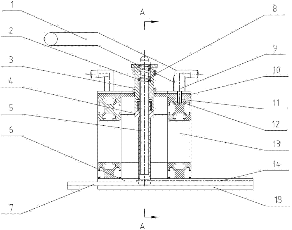
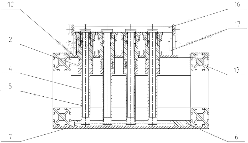
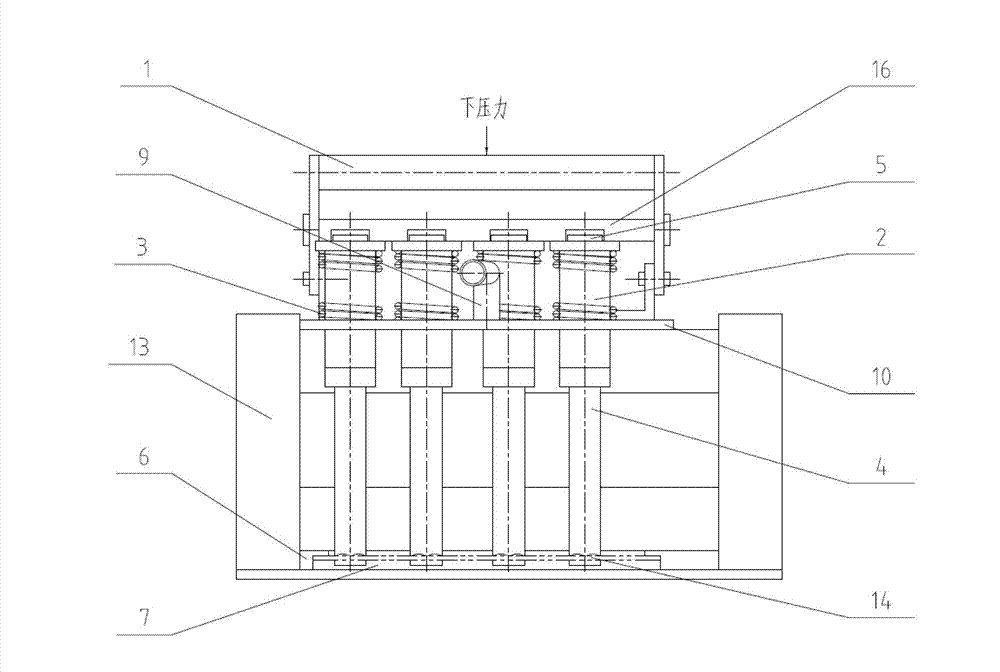
[0014] Such as figure 1 , figure 2 As shown, the processing device of the present invention is mainly composed of handle 1, support rod 2, support spring 3, cutter head 4, internal pressure head 5, binder plate 6, bottom mold 7, pressure head spring 8, locking handle 9, support Plate 10, slide block 11, groove 12, main frame 13, base plate 15, pressure bar 16, handle bracket 17 constitute. The handle 1, the support rod 2, the locking handle 9, and the handle bracket 17 are all installed on the support plate 10, the support spring 3 and the inner pressure head spring 8 are respectively set on the support rod 2 and the inner pressure head 5, and the cutter head 4 is connected with the support plate The rod 2 is threaded, the inner pressure head 5 is installed at the center of the support rod 2, the binder plate 6 is connected with the bottom mold 7 and installed on the bot...
PUM
Abstract
The invention relates to a machining device and a machining method of metal foils. The machining device mainly comprises a handle, a supporting frame, a cutter head, a material pressing plate, a supporting plate, a main frame, a base plate, a workpiece, a support, head pressing springs, a supporting rod, an inner pressing head, a locking handle, a sliding block, a groove, a pressing rod, a handle support and the like. The handle, the supporting rod, the locking handle and the handle support are all installed on the supporting plate, the springs are sleeved on the supporting rod and the inner pressing head respectively, the cutter head is in threaded connection with the supporting rod, the inner pressing head is installed in the center of the supporting rod, the material pressing plate and a bottom die are connected and then installed on the base plate, the sliding block is installed in the groove of the main frame, the main frame is installed on the base plate, and the pressing rod is installed on the handle. The machining method conducts machining and cutting on the metal foils by the adoption of the mechanical force application mode, the machining device and the machining method are high in work efficiency, the speed and precision are high, cutting on the metal foils with the different sizes can be achieved, and the machining device and the machining method are suitable for cutting the metal foils of various specifications.
Description
technical field [0001] The invention relates to a metal foil processing device and method, in particular to a metal foil processing device and a processing method for a nuclear power plant pressurized water reactor pressure vessel detection sheet, belonging to the field of nuclear industry mechanical processing. Background technique [0002] According to the regulations, the fast neutron fluence exposure to the reactor pressure vessel must be monitored during the operation of the nuclear power plant, and the in-reactor irradiation supervisory tube is usually used to achieve this purpose. The external neutron dosimeter installed outside the reactor pressure vessel can be used as an effective supplement for in-reactor radiation supervision. [0003] The external neutron dosimeter selects some specific pure metal foils, places them in the neutron environment of the reactor cavity for activation, measures the activity of the activated products after taking them out, and then cal...
Claims
Application Information
Patent Timeline
Application Date:The date an application was filed.
Publication Date:The date a patent or application was officially published.
First Publication Date:The earliest publication date of a patent with the same application number.
Issue Date:Publication date of the patent grant document.
PCT Entry Date:The Entry date of PCT National Phase.
Estimated Expiry Date:The statutory expiry date of a patent right according to the Patent Law, and it is the longest term of protection that the patent right can achieve without the termination of the patent right due to other reasons(Term extension factor has been taken into account ).
Invalid Date:Actual expiry date is based on effective date or publication date of legal transaction data of invalid patent.