

Numerical control plate shearing machine capable of preventing reduction of cutting precision
A shearing machine and precision technology, applied in the field of numerical control, can solve the problems of reduced cutting precision, deformation of the plate, and affecting the processing of metal plates, etc., and achieve the effect of reducing the cutting precision
- Summary
- Abstract
- Description
- Claims
- Application Information
AI Technical Summary
Problems solved by technology
Method used
Image

Examples
Embodiment Construction
[0021] The following will clearly and completely describe the technical solutions in the embodiments of the present invention with reference to the accompanying drawings in the embodiments of the present invention. Obviously, the described embodiments are only some, not all, embodiments of the present invention. Based on the embodiments of the present invention, all other embodiments obtained by persons of ordinary skill in the art without making creative efforts belong to the protection scope of the present invention.
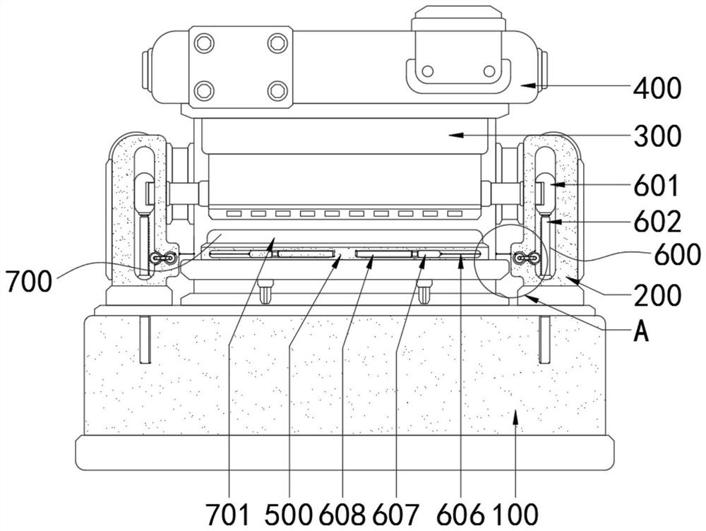
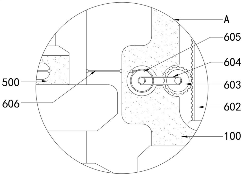
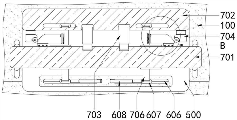
[0022] see figure 1 , a numerically controlled shearing machine that prevents the reduction of cutting accuracy, including a bottom box 100, a support column 200, a shearing knife 300, a top plate 400, a base 500, a transmission assembly 600 and an anti-scratch assembly 700, the top of the bottom box 100 and the base 500 Fixed connection, the top of the bottom box 100 is fixedly connected to the top of the base 500 and the support column 200, the left side of ...
PUM
 Abstract
Description
Claims
Application Information