
System, method and device for calibrating work machine

a work machine and work method technology, applied in soil shifting machines/dredgers, constructions, etc., can solve the problems of increasing affecting the accuracy of position detection, and complicating calibration work, so as to reduce the number of measurement points for detecting the attitude of the vehicle body and simplify the calibration work of the work machine.

Pending Publication Date: 2022-03-17
KOMATSU LTD
View PDF0 Cites 2 Cited by
  • Summary
  • Abstract
  • Description
  • Claims
  • Application Information

AI Technical Summary

Benefits of technology

[0004]The machine data is affected by tolerances in the constitutional components of the vehicle body. Therefore, variation may easily arise in the position detection accuracy of the positional sensor as indicated above due to individual work machines. In addition, the position detection accuracy may deteriorate due to wear of the constitutional components of the work machine.
[0005]The accuracy of the position of the work implement can be improved by calibrating the machine data using an external measurement apparatus such as a total station. However, the number of measurement points increases in such a case and calibration work becomes complicated.
[0006]An object of the present disclosure is to simplify the calibration work for a work machine.
[0010]According to the present disclosure, the machine data is calibrated based on the calibration data and the attitude data. The attitude data is acquired by the attitude sensor. As a result, the number of measurement points for detecting the attitude of the vehicle body can be reduced. Consequently, the calibration work for the work machine can be simplified.

Problems solved by technology

In addition, the position detection accuracy may deteriorate due to wear of the constitutional components of the work machine.
However, the number of measurement points increases in such a case and calibration work becomes complicated.

Method used


Image

  • System, method and device for calibrating work machine
  • System, method and device for calibrating work machine
  • System, method and device for calibrating work machine

Examples


Embodiment Construction

)

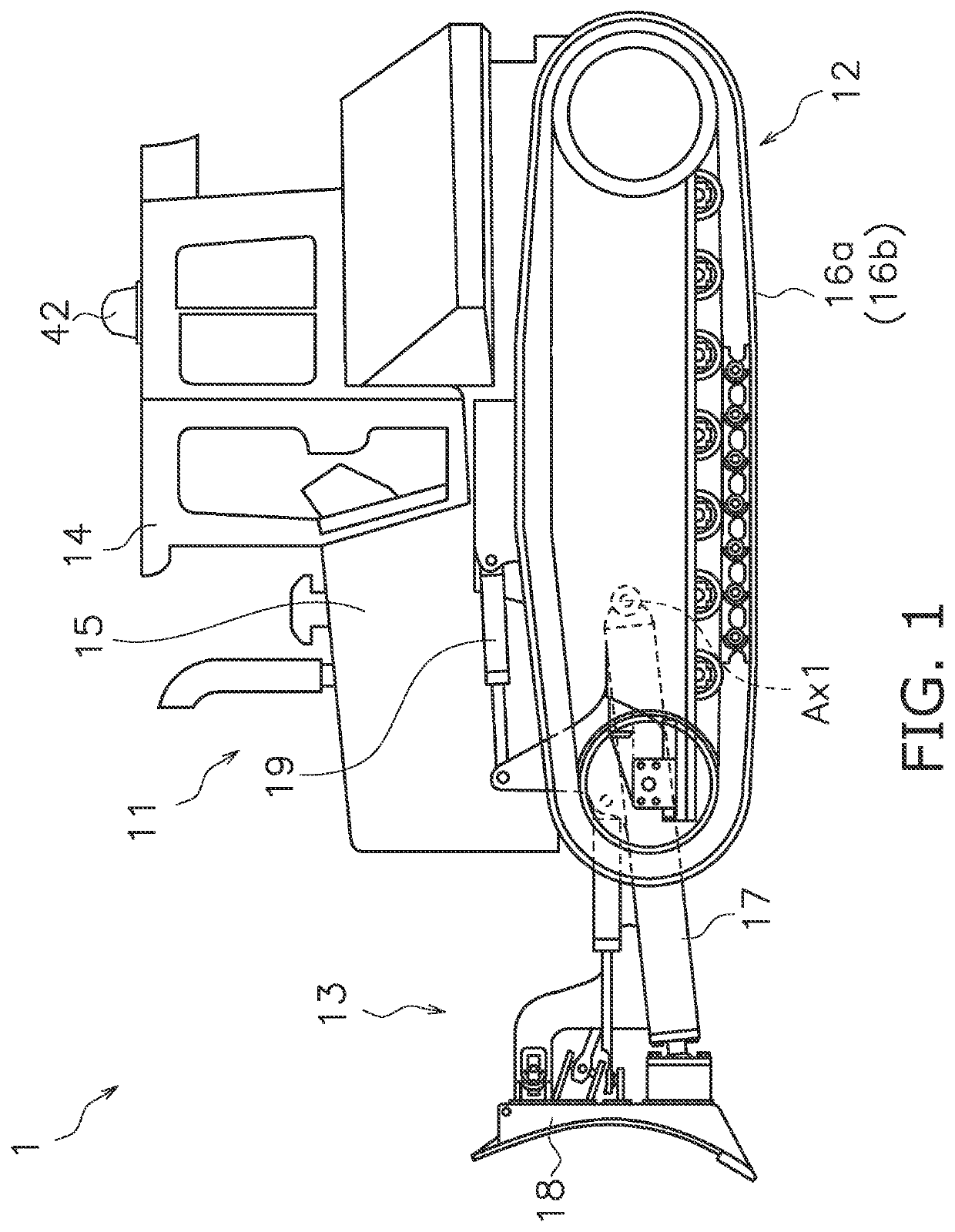
[0024]A work machine according to an embodiment is discussed hereinbelow with reference to the drawings. FIG. 1 is a side view of a work machine 1 according to the embodiment. The work machine 1 according to the present embodiment is a bulldozer. The work machine 1 includes a vehicle body 11, a travel device 12, and a work implement 13.

[0025]The vehicle body 11 has an operating cabin 14 and an engine compartment 15. An operator's seat that is not illustrated is disposed inside the operating cabin 14. The engine compartment 15 is disposed in front of the operating cabin 14. The travel device 12 is attached to a bottom part of the vehicle body 2. The travel device 12 includes left and right crawler belts 16a and 16b. Only the crawler belt 16a on the left side is illustrated in FIG. 1. The work machine 1 travels due to the rotation of the crawler belts 16a and 16b.

[0026]The work implement 13 is attached to the vehicle body 11. The work implement 1 has a lift frame 17, a blade 18, and...


PUM


Abstract

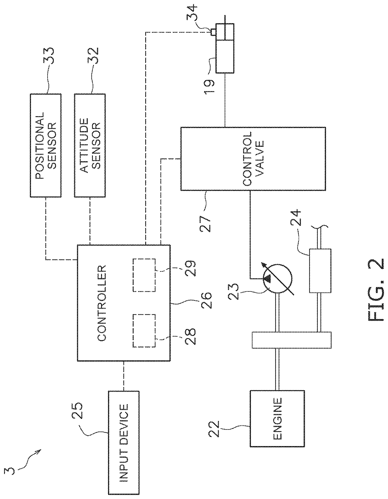
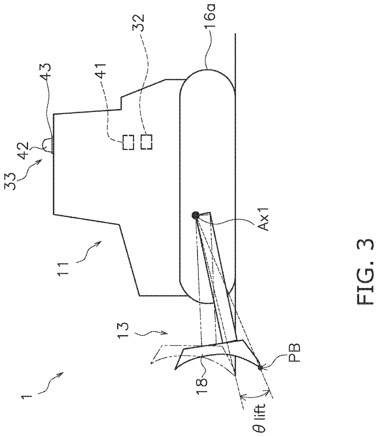
A work machine includes a vehicle body and a work implement attached to the vehicle body. A system calibrates the work machine by using an external measurement apparatus. The system includes an attitude sensor, a positional sensor attached to the vehicle body, a storage device, an input device and a processor. The attitude sensor outputs attitude data indicative of an attitude of the vehicle body. The storage device stores machine data indicative of a position of the positional sensor in a vehicle body coordinate system. The input device receives an input of calibration data including a position of a predetermined measurement point on the work machine measured by the external measurement apparatus, and a position of the positional sensor measured by the external measurement apparatus. The processor calibrates the machine data based on the calibration data and the attitude data.

Description

[0001]This application is a U.S. National stage application of International Application No. PCT / JP2020 / 006004, filed on Feb. 17, 2020. This U.S. National stage application claims priority under 35 U.S.C. § 119(a) to Japanese Patent Application No. 2019-027645, filed in Japan on Feb. 19, 2019, the entire contents of which are hereby incorporated herein by reference.BACKGROUNDField of the Invention[0002]The present disclosure relates to a system, a method, and a device for calibrating a work machine.Background Information[0003]Conventionally, techniques for detecting the position of a work machine have been proposed in a work machine such as a bulldozer. For example, Japanese Patent Laid-open No. 2018-021348 is a work machine provided with a work implement, a positional sensor, a storage device, and a controller. The work implement is attached to the vehicle body. The positional sensor detects the position of the vehicle body. The storage device stores machine data. The machine data ...

Claims


Application Information

Patent Timeline
Patent Type & Authority Applications(United States)
IPC IPC(8): E02F9/26E02F9/20
CPCE02F9/264E02F9/2025E02F9/202E02F3/841
Inventor HARADA, JUNJITAKAYAMA, KENTARO
Owner KOMATSU LTD
Learn More