Supercharge Your Innovation With Domain-Expert AI Agents!

Electronic device, PCB and electric tool

a technology of electric tools and electronic devices, applied in the field of electric tools, can solve the problems of high cost of electric tools and high purchasing costs of parts, and achieve the effect of high cos

Active Publication Date: 2022-03-17
SHENZHEN TOPBAND CO LTD
View PDF4 Cites 1 Cited by
  • Summary
  • Abstract
  • Description
  • Claims
  • Application Information

AI Technical Summary

Benefits of technology

The electronic device in this patent aims to solve the problem of high cost caused by the fact that existing electric tools use both a speed regulation switch and a commutator. The device has a cylindrical speed regulating handle with an opening and a main body with a column. The speed regulating handle is movable on the column through an elastic piece, and its opening end forms a space with the main body where the speed regulating contact and variable resistor are arranged. This prevents external contaminants like dust or water from entering and causing damage to the speed regulating contact or variable resistor. This ensures the electronic device works properly.

Problems solved by technology

Since the speed regulation switch and the commutator are usually produced by special manufacturers, the parts purchasing cost is usually high, which leads to the high cost of the electric tool.

Method used


Image

  • Electronic device, PCB and electric tool
  • Electronic device, PCB and electric tool
  • Electronic device, PCB and electric tool

Examples


embodiment 1

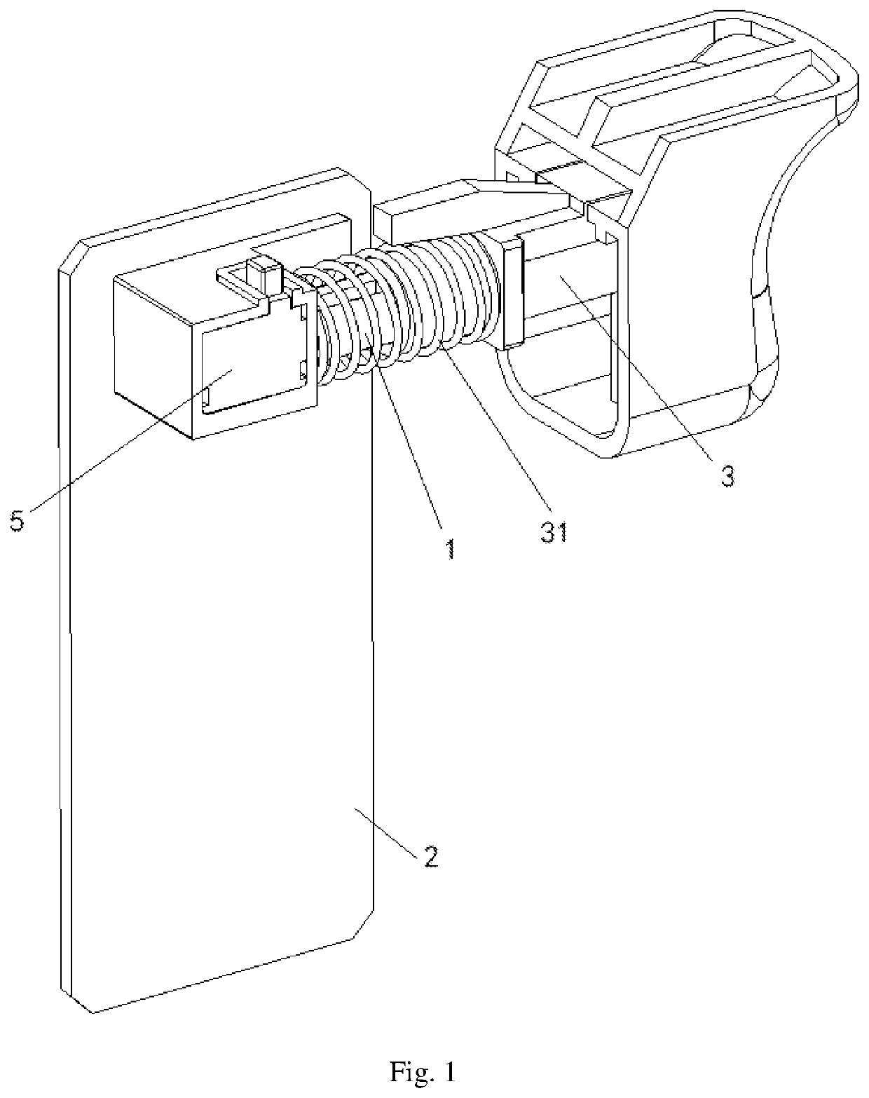
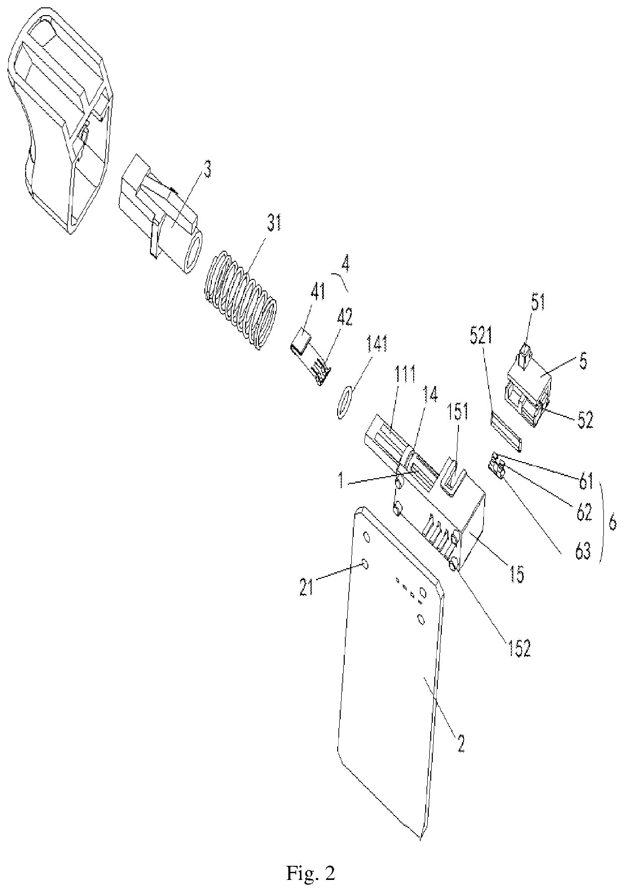
[0037]As shown in FIG. 1 and FIG. 2, the embodiment of the invention provides an electronic device, which comprises a main body 1, a first electric connecting part 11, a variable resistor 111, a speed regulating contact 4, a reversing electric connecting part, a reversing contact 6, a speed regulating handle 3 and a reversing handle 5, wherein the resistance value of the variable resistor 111 changes along the length direction;

[0038]the first electric connecting part 11 is fixedly connected with the main body 1, and one end of the first electric connecting part 11 is exposed out the main body 1;

[0039]one of the speed regulating contact 4 and the variable resistor 111 is arranged on the main body 1 and is connected with the first electric connecting part 11, and the other is arranged on the speed regulating handle 3;

[0040]one end of the speed regulating handle 3 is of a cylindrical structure and is provided with an opening at the end part; one end of the main body 1 is provided with ...

embodiment 2

[0046]On the basis of the first embodiment, the invention further provides an optional embodiment, wherein the first electric connecting part is connected with the main body in a melt adhesive curing mode; and the reversing electric connecting part is connected with the main body in a melt adhesive curing mode; the melt adhesive curing mode is an injection molding mode or a hot melt adhesive curing mode. In the embodiment of the invention, the first electric connecting part, the reversing electric connecting part and the main body are connected in a melt adhesive curing mode, so that the mounting process of the first electric connecting part, the reversing electric connecting part and the main body is simplified, make the first electric connecting part, the reversing electric connecting part and the main body into a whole, prevent the first electric connecting part, the reversing electric connecting part and the main body fall off, improve the stability of the electronic device, the...

embodiment 3

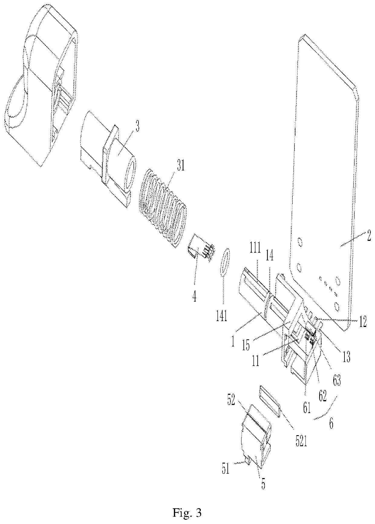
[0047]On the basis of the first embodiment, the present invention further provides an alternative embodiment. As shown in FIG. 2, the speed regulating contact 4 may include a first connecting end 41 and a first elastic sheet 42 connected to the first connecting end 41, the first connecting end 41 is connected to the inner wall of the speed regulating handle 3, and the first elastic sheet 42 is in contact with the variable resistor 111; one end of the main body 1 may be circumferentially provided with a first annular groove 14, and a first sealing ring 141 is sleeved in the first annular groove 14; an inner wall of the speed regulating handle 3 is connected to an outer wall of one end of the main body 1 through the first seal ring 141, and the aforementioned first space is formed in the speed regulating handle 3.

[0048]Wherein, the elastic piece 31 can be a spring, the speed regulating handle 3 can realize elastic connection with one end of the main body 1 through the spring, that is,...


PUM


Abstract

The invention provides an electronic device, a PCB and an electric tool; comprises a main body, a first electric connecting part, a variable resistor, a speed regulating contact, a reversing electric connecting part, a reversing contact, a speed regulating handle and a reversing handle, the first electric connecting part is fixedly connected with the main body, and one end of the first electric connecting part is exposed out of the main body; one end of the speed regulating handle is of a cylindrical structure, the end part of the speed regulating handle is provided with an opening, one end of the main body is provided with a column, the opening end of the speed regulating handle is movably sleeved on the column through an elastic piece and forms a first space with the main body; the speed regulating contact and the variable resistor are arranged in the first space.

Description

BACKGROUND OF THE INVENTION1. Technical Field[0001]The invention belongs to the technical field of electric tools, and particularly relates to an electronic device, a PCB and an electric tool.2. Description of Related Art[0002]Electric tool is a kind of tool which is held by the operator's hand to operate and driven by a small power motor or electromagnet through a transmission mechanism to operate the working head, the electric tool has a wide variety of type, and has the advantages of convenient carrying, simple operation, multiple functions, reduce labor intensity, improving work efficiency and the like, it is widely used in construction, housing decoration, automobile assembly, construction machinery and other fields, and also entered the family in large numbers.[0003]At present, that electric tool usually has a speed regulation function and a commutating function to meet the requirement of different working conditions, the speed regulation function of the electric tool is usual...

Claims


Application Information

Patent Timeline
Patent Type & Authority Applications(United States)
IPC IPC(8): H01H9/06H01H15/16H01H15/00
CPCH01H9/061H01H15/005H01H15/16H01H9/063
Inventor LIANG, SHILINCHEN, JIANCHEN, HONGYUANLUO, SHILI, JUNBIAOHUANG, HAIZHENG, SHUQUAN
Owner SHENZHEN TOPBAND CO LTD
Features
  • R&D
  • Intellectual Property
  • Life Sciences
  • Materials
  • Tech Scout
  • Unparalleled Data Quality
  • Higher Quality Content
  • 60% Fewer Hallucinations
Learn More