Circumferential wear bands for oilfield tubulars

Pending Publication Date: 2022-03-31
MOORE RUSSEL
View PDF5 Cites 0 Cited by
  • Summary
  • Abstract
  • Description
  • Claims
  • Application Information

AI Technical Summary

Benefits of technology

[0009]In general terms, the present disclosure teaches non-limiting embodiments of circumferential wear bands that can be formed on a steel pipe string, at selected intervals along the length of the pipe string, to protect components of the pipe string from abrasive wear caused by sliding and/or rotating contact with interior su

Problems solved by technology

As the pipe (or tubing) string moves through the well, with or without rotation, it will rub against the inner surfaces of the steel casing, causing abrasion and wear to the casing and to the pipe (or tubing) carrying the mud motor.
However, it is very expensive, both in terms of initial cost of the subs and in terms of the cost of applying remedial hardbanding to worn subs.
The process of drilling out frac plugs in a horizontal well can take a number of days, and due to depth, torque is critical.
With very deep drill-outs in a devia

Method used


Image

  • Circumferential wear bands for oilfield tubulars
  • Circumferential wear bands for oilfield tubulars
  • Circumferential wear bands for oilfield tubulars

Examples


Example

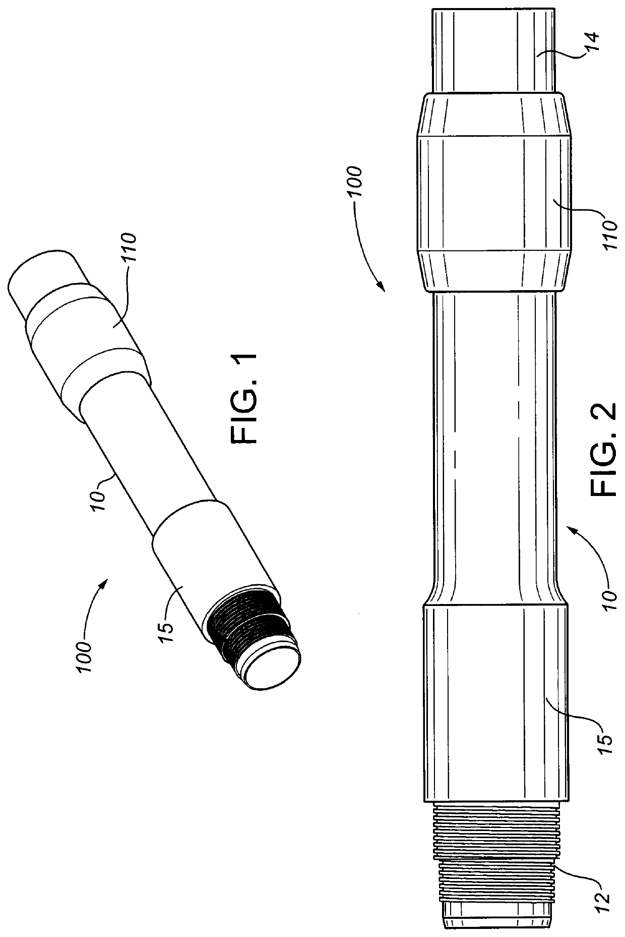
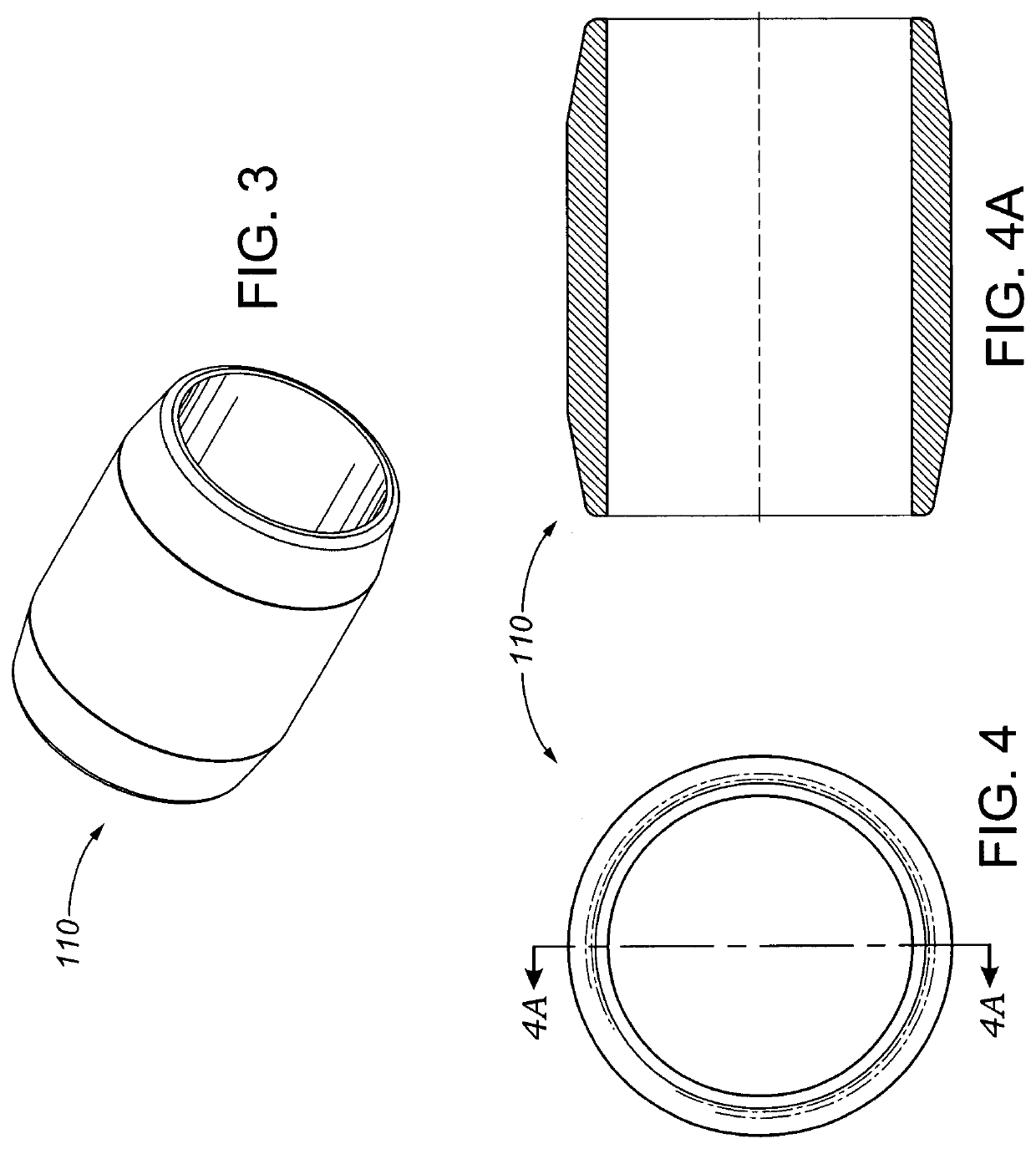
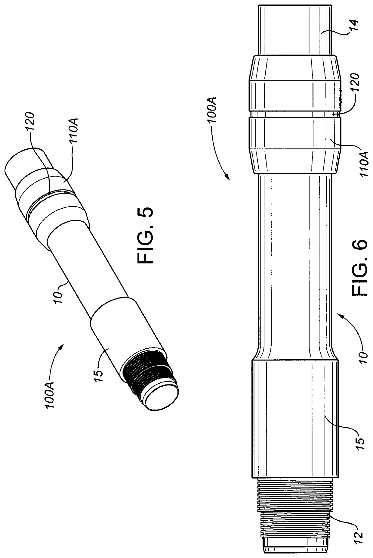
[0034]FIGS. 1 to 4A illustrate an embodiment 100 of a wear band assembly comprising a pipe sub 10 having a fixed wear band 110 injection-moulded onto pipe sub 10 in accordance with the present disclosure. Pipe sub 10 is shown as having a double-threaded pin end 12, a box end 14, and an upset section 15, with wear band 110 being formed at a location proximal to upset section 15 and having a greater outer diameter than upset section 15, such that wear band 110 will contact the surfaces of the bore of a casing string in which a pipe string carrying pipe sub 10 is disposed, and thus will prevent upset section 15 and from contacting the casing bore surfaces. However, this represents only one non-limiting example of a tubular member having a wear band 110, and embodiments in accordance with the present disclosure are not limited to or restricted in any way to any particular characteristics of the tubular member carrying wear band 110. Wear bands in accordance with the present disclosure c...


PUM


Abstract

A wear band assembly for a pipe string operating inside a casing string includes a fixed cylindrical wear band made from a non-metallic, abrasion-resistant, low-friction material injection-moulded onto a pipe joint or sub incorporated into the pipe string, and optionally having a circumferential wear indicator groove. In an alternative embodiment, the wear band assembly includes a rotatable wear band comprising mating cylindroid sections rotatably disposed within an annular recess formed in a circumferential collar injection-moulded onto the pipe or sub. The rotatable wear band initially projects radially beyond the collar and is rotatable relative to the pipe or sub, allowing the wear band to rotate relative to the casing when in rotational contact therewith, thereby reducing resultant wear to the wear band, and reducing torque in the pipe string due to contact with the casing.

Description

FIELD OF THE DISCLOSURE[0001]The present disclosure relates in general to means for protecting against abrasive wear of a tubular string running inside a larger tubular string, and relates in particular to means for protecting against abrasive wear to tubular strings used to install and remove frac plugs in vertical, horizontal, and deviated oil and gas wells.BACKGROUND[0002]During a typical “well frac” (i.e., fraccing operation) for an oil or gas well, a frac fluid carrying a proppant (typically sand or ceramic particles) is pumped under high pressure into the subsurface reservoir through perforations in the well casing, in order to fracture the formation and thus increase the flow of formation fluids (e.g., gas and / or crude oil) to the well. Frac plugs are commonly used to isolate individual zones of a well during “plug-and-perf” completion operations in vertical, deviated, and horizontal wells. The frac plugs are set using wireline, coil tubing, or threaded pipe. A one-way intern...

Claims


Application Information

Patent Timeline
IPC IPC(8): E21B17/10
CPCE21B17/1085
Inventor MOORE, RUSSEL
Owner MOORE RUSSEL
Why Eureka
Try Eureka