Flow control method, system and apparatus

Pending Publication Date: 2022-03-31
G W LISK
View PDF5 Cites 0 Cited by
  • Summary
  • Abstract
  • Description
  • Claims
  • Application Information

AI Technical Summary

Benefits of technology

This patent describes a fuel flow control apparatus for an engine. The apparatus includes a manifold, a solenoid operated proportional pressure regulator, a solenoid proportional flow control valve, and a solenoid fuel ON / OFF shut-off valve. The ultimate goal of the apparatus is to control the flow of fuel from the engine to the engine intake during different operating conditions, and to prevent fuel flow when the engine is motoring. The technical effects of this apparatus include improved engine performance and efficiency, reduced emissions, and improved fuel utilization.

Problems solved by technology

However, the flow control valve typically allows some level of internal leakage that enables a small amount of fuel to escape to the engine intake.

Method used


Image

  • Flow control method, system and apparatus
  • Flow control method, system and apparatus
  • Flow control method, system and apparatus

Examples


Embodiment Construction

[0039]It is to be understood that the invention may assume various alternative orientations and step sequences, except where expressly specified to the contrary. It is also to be understood that the specific assemblies and systems illustrated in the attached drawings and described in the following specification are simply exemplary embodiments of the inventive concepts defined herein. Hence, specific dimensions, directions, or other physical characteristics relating to the embodiments disclosed are not to be considered as limiting, unless expressly stated otherwise. Also, although they may not be, like elements in various embodiments described herein may be commonly referred to with like reference numerals within this section of the application.

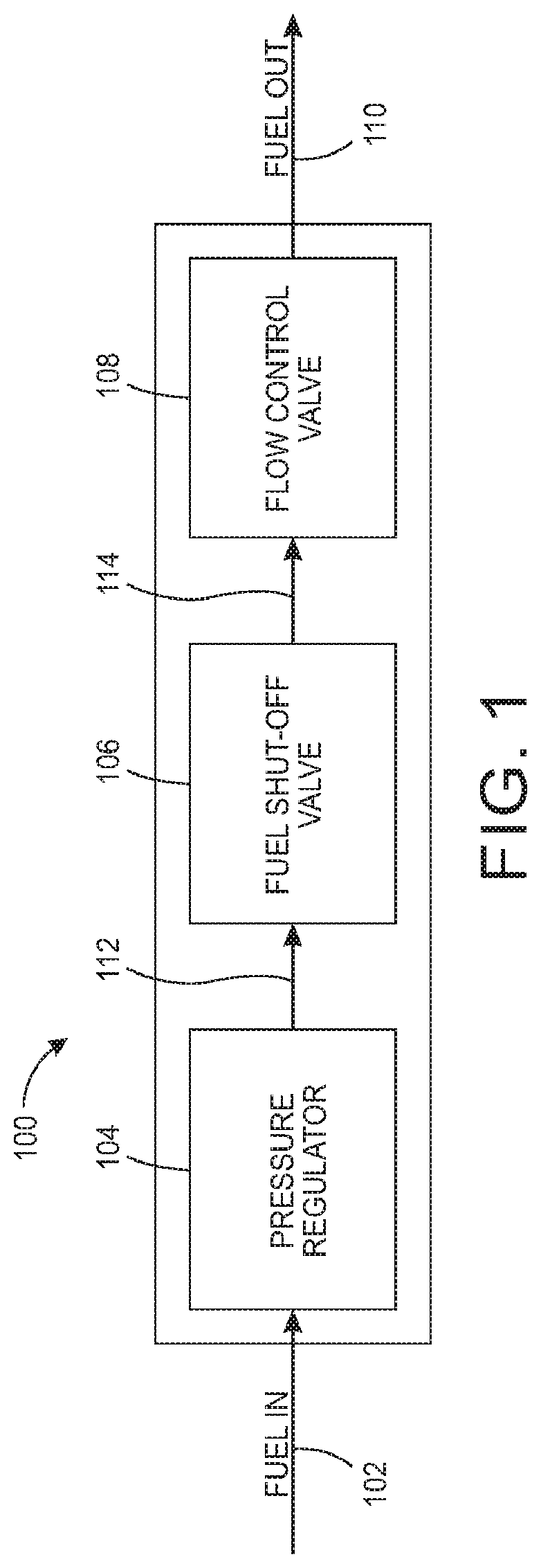
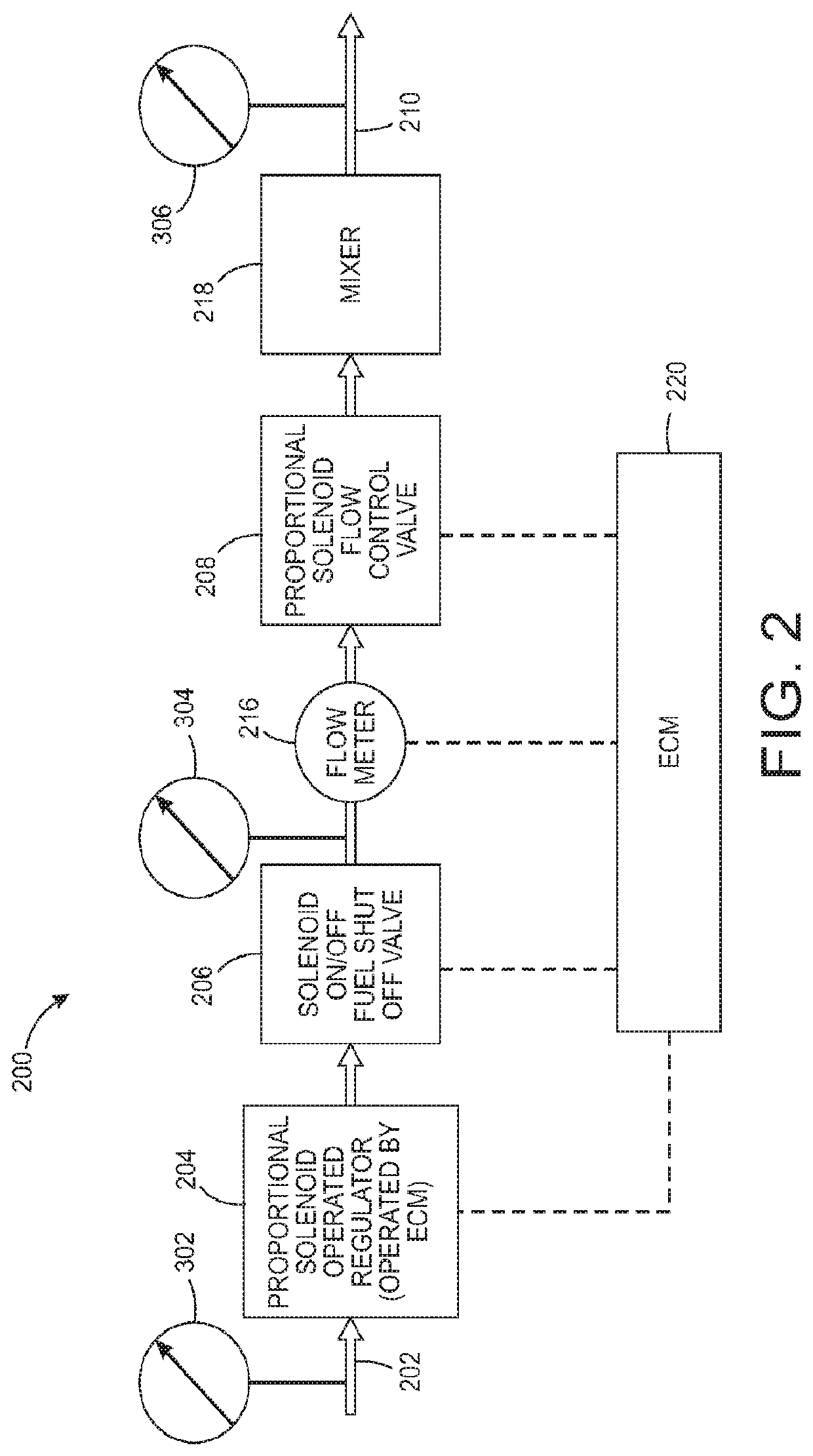
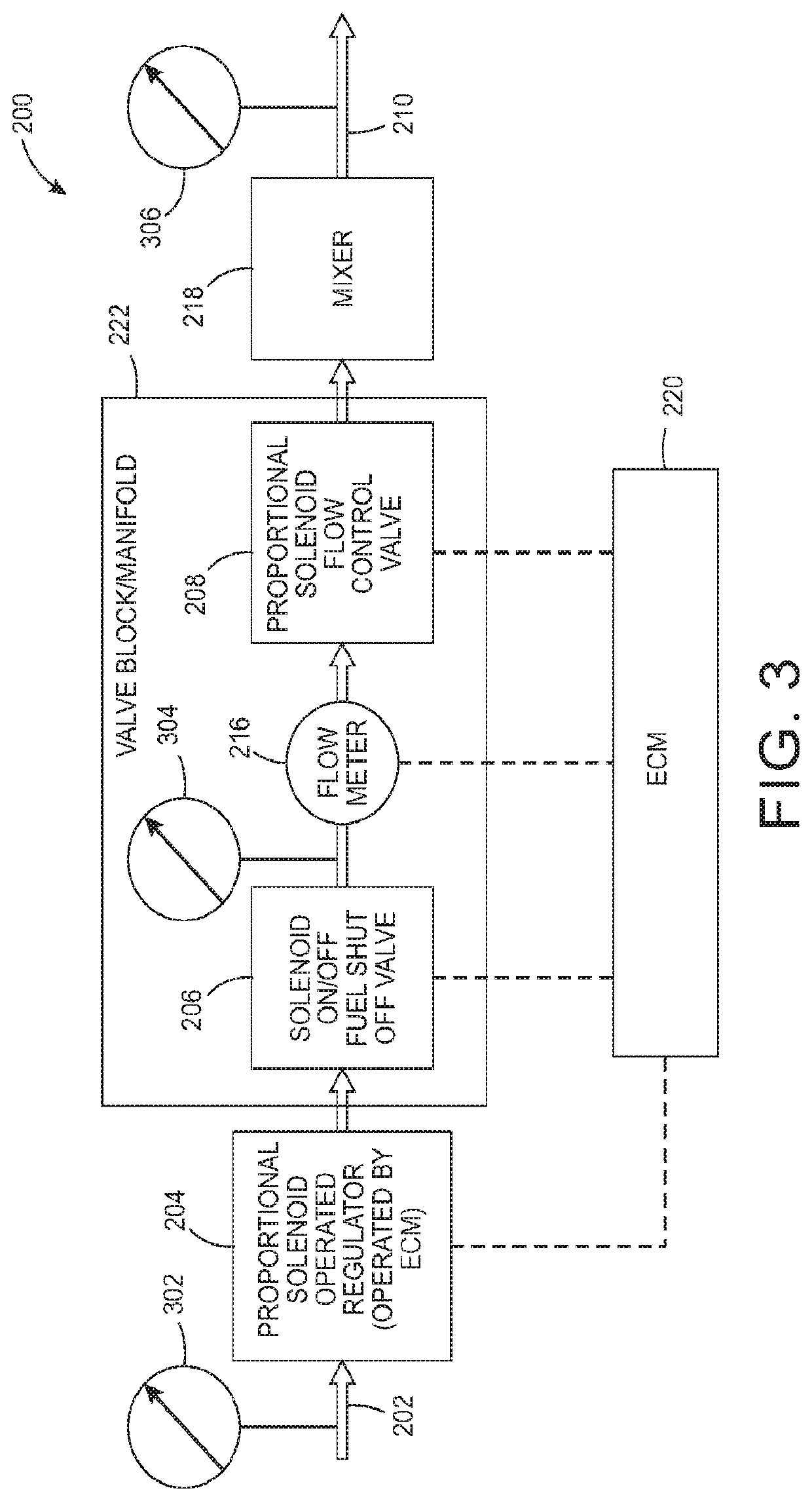
[0040]There remains a need for a fuel flow control system capable of improved performance and reliability. The fuel flow control system of the present disclosure provides several performance and reliability advantages over existing convention...


PUM


Abstract

Presented is a method, system and apparatus for fuel flow control. An exemplary fuel flow control apparatus includes a fuel inlet operable to receive a flow, and a fuel shut-off valve fluidly connected to receive the flow from the fuel inlet, the fuel shut-off valve is operable to allow the flow in a first configuration and prevent the flow in a second configuration. The apparatus further includes a pressure regulator fluidly connected to receive the flow from the fuel shut-off valve, a flow control valve fluidly connected to receive the flow from the pressure regulator, the flow control valve comprising a position sensor operable to sense a position of the flow control valve, an injector fluidly connected in parallel to the flow control valve to receive the flow from the pressure regulator, and a fuel outlet.

Description

BACKGROUND OF THE INVENTIONField of the Invention[0001]The present disclosure relates generally to fluid pressure regulators, and more particularly to a multi-stage pressure regulating system for fuel.Description of Related Art[0002]Gaseous fuels such as propane and natural gas may be stored in pressurized vessels at high pressure. Conventional internal combustion engines do not operate with gaseous fuels stored at high pressure. Therefore, fuel systems may be utilized to reduce the pressure of the fuel entering the engine intake.[0003]It is common practice with natural gas fuel systems to cut off fuel supply to the engine during motoring to help reduce emissions. Motoring occurs when there is no load applied to the engine. Conventional systems do this by closing a flow control valve, thereby sealing off fuel supply to the engine. However, the flow control valve typically allows some level of internal leakage that enables a small amount of fuel to escape to the engine intake.BRIEF S...

Claims


Application Information

Patent Timeline
IPC IPC(8): F02M21/02F02M69/18
CPCF02M21/0239F02M69/18F02M69/16F02M21/0218Y02T10/30F02D19/022F02D41/123F02D41/0027F02D19/027
Inventor TYLER, JEFFERY A.TRAPASSO, DAVID J.PEONE, ZACCARIEJOHNSON, DANIELREID, AMANDA
Owner G W LISK
Why Eureka
Try Eureka