Fuel tank made of polyketone and method of manufacturing the same

Active Publication Date: 2017-08-24
JPC AUTOMOTIVE
View PDF3 Cites 0 Cited by
  • Summary
  • Abstract
  • Description
  • Claims
  • Application Information

AI Technical Summary

Benefits of technology

The present invention provides a fuel tank made of polyketone and a method of manufacturing it using a machine that instantly bonds an upper cover and lower cover together, resulting in automated production and cost reduction. The fuel tank is made with sufficient rigidity due to the rigidity of polyketone without the necessity for an additional reinforcing member, making it a lightweight tank. The upper and lower covers are injection-molded using polyketone to improve rigidity. The fuel tank includes a partition to prevent fuel flow and a support protrusion can be used to support a pressurization force on the covers.

Problems solved by technology

However, the method of manufacturing the fuel tank disclosed in Patent Document 1, in which the rigidity of the fuel tank is reinforced and the bonding portion thereof is supported through additional post-processing (fixing rods / clamps, fiber, additional double injection molding, or dovetail process using thermosetting resin) after the injection-molding process, has limitations pertaining to mass production and cost reduction.
Further, due to the limits of the properties of the material composing the fuel tank, the rigidity of the fuel tank must be reinforced through an additional reinforcement process (fixing rods, fiber, double injection molding, or dovetail process) after the bonding process, thus leading to an increase in weight and cost.
However, in the method of manufacturing the fuel tank disclosed in Patent Document 2, in which the first molded product made by the first blow-molding process is cut, a rigidity-reinforcing material is inserted into the first molded product and the second blow-molding process is conducted on the rigidity-reinforcing material, there are limitations in mass production and cost reduction due to the additional post-processing and manual tasks.
Further, due to the characteristics of the blow molding, it is not possible to form partitions for preventing the flow noise in the fuel tank disclosed in the Patent Document 2.
Furthermore, the insertion of an additional rigidity-reinforcing material inevitably results in an increase in weight.

Method used


Image

  • Fuel tank made of polyketone and method of manufacturing the same
  • Fuel tank made of polyketone and method of manufacturing the same
  • Fuel tank made of polyketone and method of manufacturing the same

Examples


Embodiment Construction

[0030]Advantages and features of the present invention and methods for achieving them will be made clear from the embodiments described below in detail with reference to the accompanying drawings. The present invention may, however, be embodied in many different forms and should not be construed as being limited to the embodiments set forth herein. Rather, these embodiments are provided so that this disclosure will be thorough and complete, and will fully convey the scope of the invention to those skilled in the art. The present invention is merely defined by the scope of the claims. Like reference numerals refer to like elements throughout the specification.

[0031]Hereinafter, a fuel tank made of polyketone and a method of manufacturing the same will be described in detail in connection with preferred embodiments of the present invention with reference to the accompanying drawings.

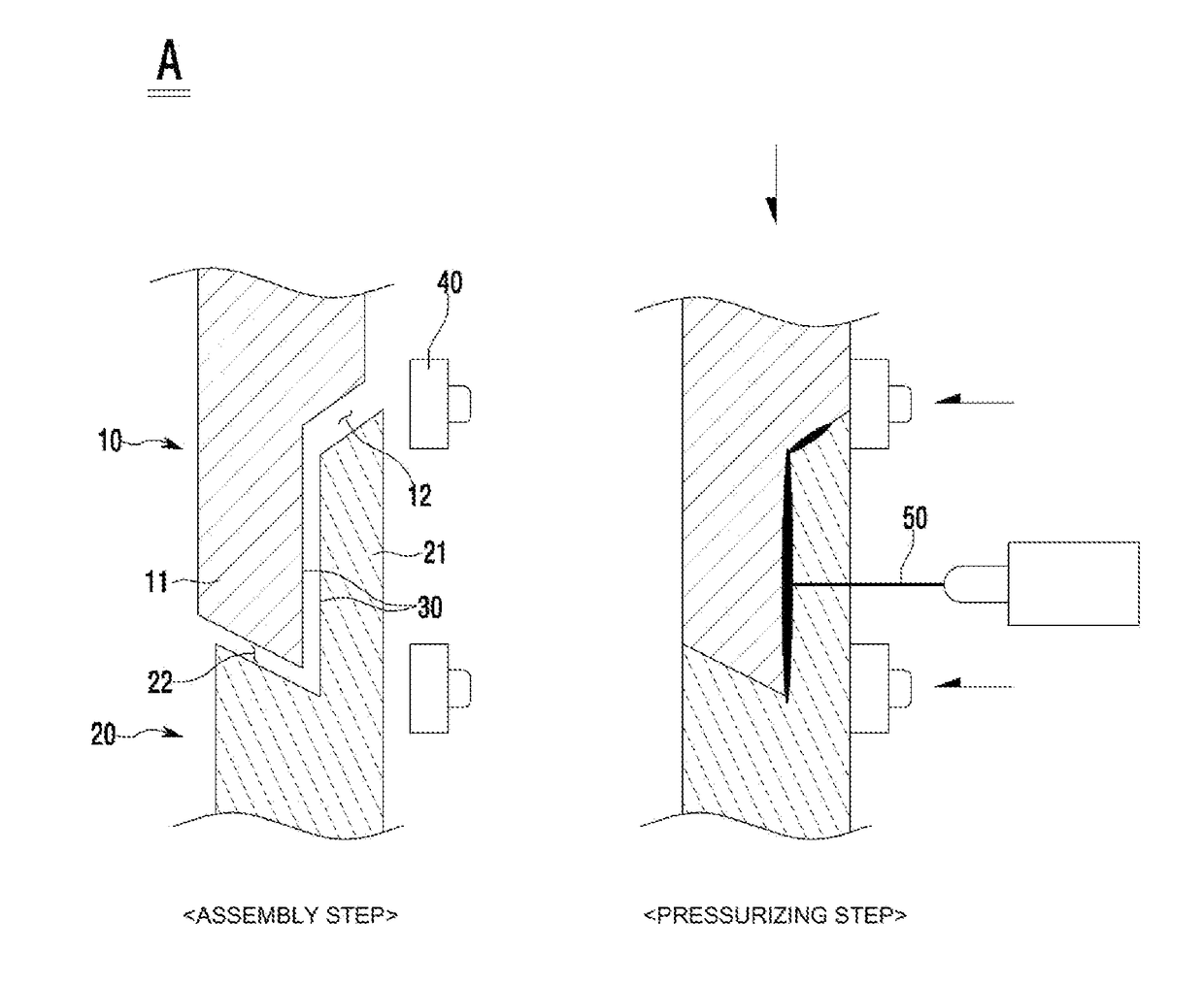
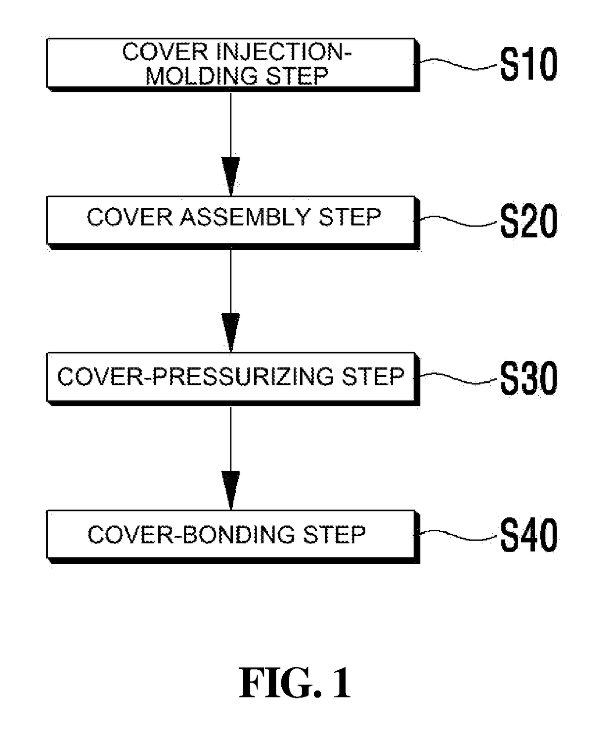
[0032]FIG. 1 is a flowchart showing a method of manufacturing a fuel tank using polyketone according to...


PUM

PropertyMeasurementUnit
Forceaaaaaaaaaa
Stiffnessaaaaaaaaaa

Abstract

Provided are a fuel tank made of polyketone and a method of manufacturing the same. The method includes injection-molding an upper cover and a lower cover using an injection-molding machine, placing the upper cover and the lower cover at a relatively high position and a relatively low position, respectively, assembling the upper cover and the lower cover with each other, and bonding contact surfaces between the upper cover and the lower cover to each other using a laser beam. Since the upper cover and the lower cover are formed at the same time and are bonded to each other immediately after being assembled by a machine, it is possible to achieve automated production, mass production and remarkable cost reduction. Further, since the fuel tank has sufficient rigidity due to the rigidity of polyketone without an additional reinforcing member, it is possible to manufacture a lightweight fuel tank.

Description

BACKGROUND OF THE INVENTION[0001]Field of the Invention[0002]The present invention relates to a fuel tank made of polyketone and a method of manufacturing the same, and more particularly, to a fuel tank made of polyketone and a method of manufacturing the same, which enables automated production and mass production of a fuel tank by forming two components, namely an upper cover and a lower cover, at the same time and bonding them to each other immediately after assembling them with each other using a machine.[0003]Description of the Related Art[0004]In general, a vehicle fuel device is a device for supplying a fuel-air mixture to an engine, and includes a vaporizer for forming a fuel-air mixture and supplying the same to an engine or an injector for spraying a fuel into a combustion chamber of an engine, a fuel pump for supplying a filtered fuel to the vaporizer or the injector, and a fuel tank for storing a fuel therein.[0005]The aforementioned components are connected to each othe...

Claims


Application Information

Patent Timeline
IPC IPC(8): B29C45/00B29C65/16B60K15/03
CPCB29C45/006B60K15/03006B60K15/03177B29C65/16B29L2031/7172B60K2015/03493B29C2045/007B29K2061/00B60K2015/03032B29C45/0001B29C65/1693B29C66/10B29C69/00B29K2073/00B29C65/1635B29C65/5042B29C65/5057B29C65/5071B29C65/5085B29C65/7841B29C66/12449B29C66/12463B29C66/12469B29C66/1282B29C66/12841B29C66/1286B29C66/12861B29C66/1312B29C66/14B29C66/301B29C66/54B29C66/543B29C66/71B29C66/8322B29C66/83221B60K2015/0346B29K2077/00
Inventor YUN, GWAN WON
Owner JPC AUTOMOTIVE
Why Eureka
Try Eureka