
Exhaust Gas Purifying Apparatus for Internal Combustion Engine

a technology for exhaust gas purification and internal combustion engines, which is applied in mechanical equipment, machines/engines, electric control of exhaust gas treatment, etc., can solve the problems of fuel not being atomized sufficiently before reaching the exhaust gas purification, and achieve the effects of preventing fuel from flowing into the intake system, facilitating dispersion of fuel into exhaust gas, and facilitating atomization of fuel

Inactive Publication Date: 2009-04-09
TOYOTA JIDOSHA KK
View PDF7 Cites 11 Cited by
  • Summary
  • Abstract
  • Description
  • Claims
  • Application Information

AI Technical Summary

Benefits of technology

[0006]Since the flow-passage cross section of the communication passage is smaller than those of the first branch passage and the second branch passage, if the flow rate of exhaust gas is the same, the flow velocity of exhaust gas in the communication passage becomes higher than that of exhaust gas in the exhaust passage. Since, in the exhaust gas purifying apparatus of the invention, the communication passage is provided with a fuel addition valve, it is possible to add fuel to exhaust gas having high flow velocity. Therefore, it is possible to facilitate dispersion of fuel into exhaust gas, and facilitate atomization of fuel.
[0007]The exhaust gas purifying apparatus of the invention further includes a first turbocharger, a turbine of which is provided in the first branch passage, and a second turbocharger, a turbine of which is provided in the second branch passage, wherein the communication passage may connect an upstream section of the first branch passage from the turbine of the first turbo charger and an upstream section of the second branch passage from the turbine of the second turbocharger with each other. In this case, exhaust gas which has passed through the communication passage is introduced into the turbine of the first turbocharger or the second turbocharger. Therefore, when fuel is added to exhaust gas from the fuel addition valve, fuel and exhaust gas can be stirred by the turbine of the first turbocharger or the second turbocharger. Thus, it is possible to further facilitate dispersion of fuel into exhaust gas, and facilitate atomization of fuel.
[0008]In the exhaust gas purifying apparatus of the invention, the exhaust flow control device controls flow of exhaust gas such that exhaust gas emitted from the first group of cylinders is introduced into the second branch passage through the communication passage when the predetermined exhaust flow switching condition is established, and the communication passage may be provided with an exhaust gas purifying catalyst located closer to the first branch passage than the fuel addition valve. In this case, since particulate matter (PM) in exhaust gas can be removed by the exhaust gas purifying catalyst, it is possible to prevent PM from adhering to the fuel addition valve. Accordingly, it is possible to suppress the clogging of the injection opening of the fuel addition valve, and thus an amount of fuel to be added to exhaust gas can be appropriately injected from the fuel addition valve.
[0009]In the exhaust gas purifying apparatus of the invention, the exhaust flow control device controls flow of exhaust gas such that exhaust gas emitted from the first group of cylinders is introduced into the second branch passage through the communication passage when the predetermined exhaust flow switching condition is established, and an EGR passage for returning a part of exhaust gas into an intake system of the internal combustion engine may be connected to an upstream section of the first branch passage from a position where the first branch passage and the communication passage are connected to each other. If the EGR passage is connected to such section, it is possible to prevent fuel added from the fuel addition valve from flowing into the intake system.
[0011]If the EGR passage is connected to near the fuel addition valve, fuel added to exhaust gas from the fuel addition valve might flow into the intake system of the internal combustion engine through the EGR passage. According to another exhaust gas purifying apparatus of the invention, the EGR passage is connected to a location which becomes upstream side of the fuel addition valve when exhaust gas emitted from the first group of cylinders is controlled by the exhaust flow control device to flow into the second branch passage through the communication passage. Therefore, even when fuel is added from the fuel addition valve, it is possible to prevent fuel from flowing into the EGR passage. Thus, it is possible to prevent fuel from flowing into the intake system.
[0012]As explained above, according to the present invention, since the fuel addition valve is provided in the communication passage having a higher flow velocity of exhaust gas than that in the exhaust passage, it is possible to facilitate dispersion of fuel into exhaust gas, and facilitate atomization of fuel.

Problems solved by technology

When the flow velocity of exhaust gas is low at the injection of fuel, the fuel is not readily dispersed in exhaust gas, and thus, the fuel might not be atomized sufficiently before reaching the exhaust gas purifying catalyst.

Method used


Image

  • Exhaust Gas Purifying Apparatus for Internal Combustion Engine
  • Exhaust Gas Purifying Apparatus for Internal Combustion Engine
  • Exhaust Gas Purifying Apparatus for Internal Combustion Engine

Examples


Embodiment Construction

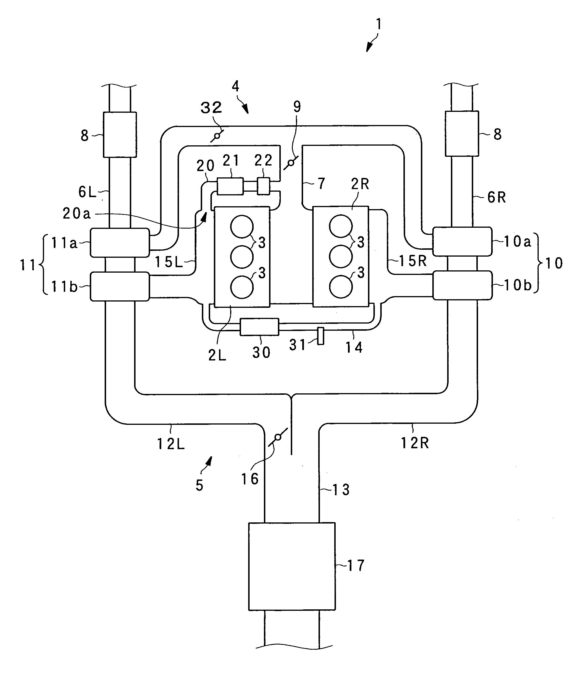
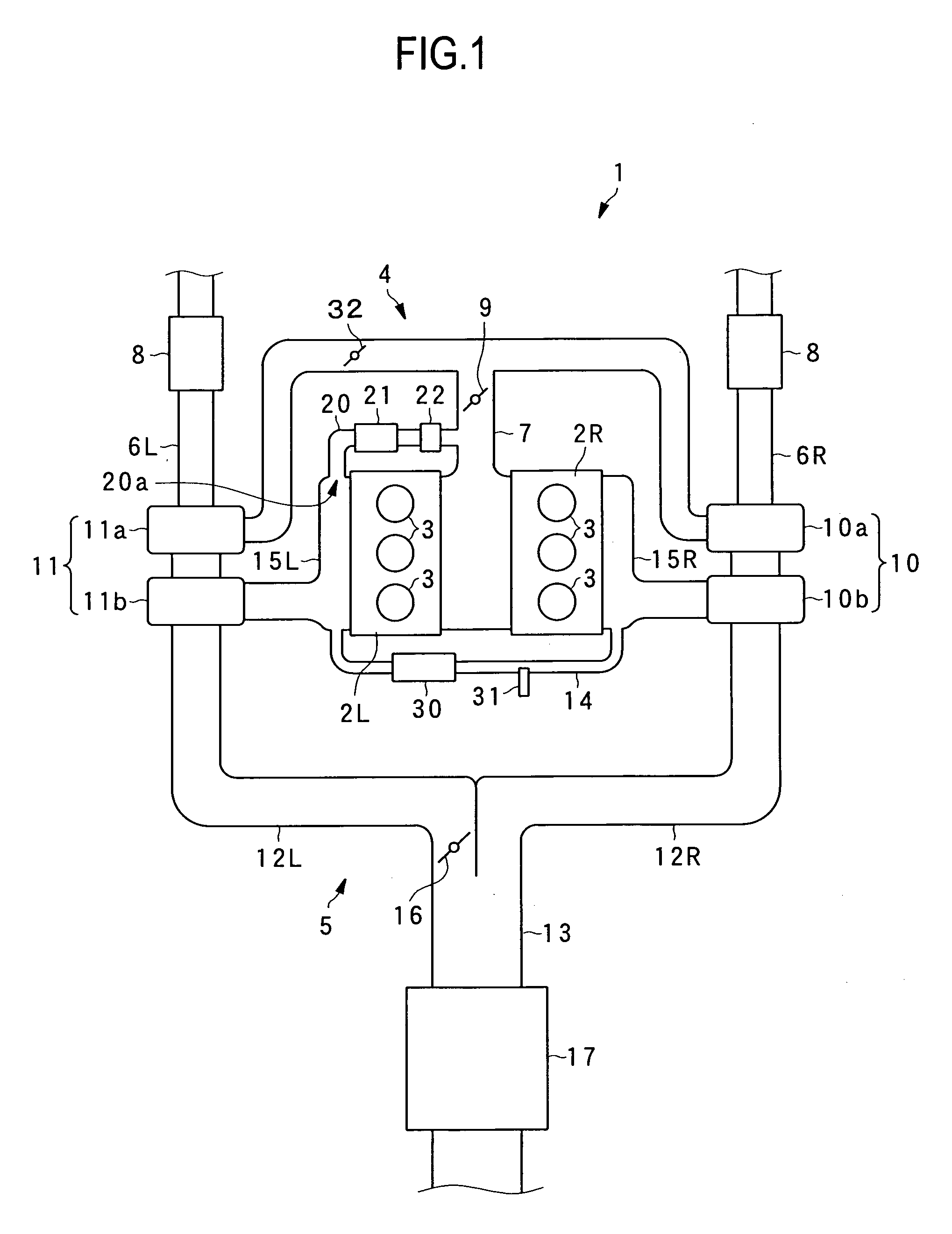
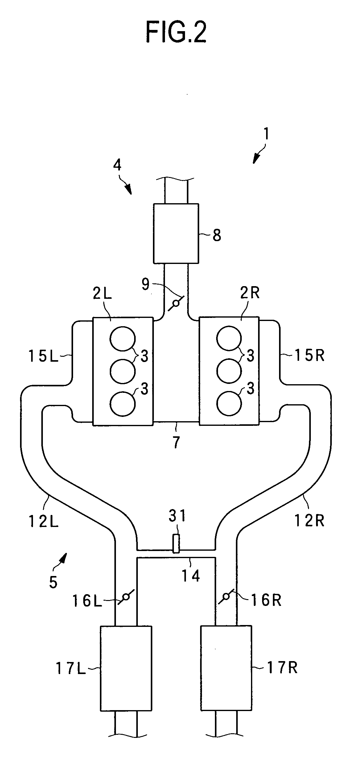
[0030]FIG. 1 shows one embodiment for an internal combustion engine in which an exhaust gas purifying apparatus according to the present invention is incorporated. As shown in FIG. 1, the internal combustion engine is a six-cylinder V-type diesel engine 1 having three cylinders 3 respectively for left and right banks 2L and 2R. The engine 1 is mounted as a driving power source in a vehicle such as an automobile. In the engine 1, the cylinders 3 on the left bank 2L constitute one group of cylinders, and the cylinders 3 on the right bank 2R constitute the other group of cylinders.

[0031]The engine 1 includes an intake passage 4 for introducing intake air into the cylinders 3, an exhaust passage 5 for introducing exhaust gas emitted from the cylinders 3 to a predetermined exhaust position, a main turbocharger 10 and a sub turbocharger 11. The intake passage 4 includes branch intake passages 6L and 6R provided in correspondence with the left and right banks 2L and 2R, and a merging intak...


PUM


Abstract

An exhaust gas purifying apparatus for an internal combustion engine is provided. The apparatus includes a first group of cylinders; a second group of cylinders; an exhaust passage having a first branch passage connected to the first group of cylinders and a second branch passage connected to the second group of cylinders; a communication passage which connects the first branch passage and the second branch passage with each other; an exhaust gas purifying device provided in the exhaust passage and located downstream from a position connected to the communication passage; and an exhaust flow control device for controlling flow of exhaust gas such that exhaust gas emitted from one of the first group of cylinders and the second group of cylinders is introduced into the branch passage connected to the other group of cylinders through the communication passage when a predetermined exhaust flow switching condition is established, wherein a flow-passage cross section of the communication passage is smaller than those of the first branch passage and the second branch passage, and the communication passage is provided with a fuel addition valve for adding fuel to exhaust gas from upstream of the exhaust gas purifying device.

Description

TECHNICAL FIELD[0001]The present invention relates to an exhaust gas purifying apparatus for an internal combustion engine having two groups of cylinders, to which different exhaust passages are connected and the exhaust passages of the two groups of cylinders are connected to each other through a communication passage.BACKGROUND ART[0002]There is known a V-type internal combustion engine, in which different exhaust passages are connected to groups of cylinders of banks, and the exhaust passages are in communication with each other through a communication passage (see Japanese Patent Application Laid-open No. 5-106449).[0003]As an exhaust gas purifying apparatus for an internal combustion engine, there is known a regenerative exhaust gas purifying catalyst such as a storage-reduction type NOx catalyst. The recovery process of the exhaust gas purifying catalyst is carried out by adding fuel to exhaust gas, and making an air fuel ratio of exhaust gas richer than the theoretical air fu...

Claims


Application Information

Patent Timeline
Patent Type & Authority Applications(United States)
IPC IPC(8): F01N9/00F01N13/08
CPCF01N3/0842F01N13/011F01N3/0885F01N3/2033F01N13/107F01N2240/36F01N2610/03F02B37/007F02B75/22F02M25/0711F02M25/0727F02M25/0749Y02T10/144Y02T10/26F01N3/0871F02M26/08F02M26/23F02M26/43Y02T10/12
Inventor SUGIYAMA, TOSHIHISA
Owner TOYOTA JIDOSHA KK
Learn More