
Head-up display, vehicle display system, and vehicle display method

a head-up display and vehicle technology, applied in static indicating devices, instruments, navigation instruments, etc., can solve problems such as increased cost, heat damage to display devices, and inconvenience of image display, so as to reduce discomfort, improve usability, and suppress processing load

Pending Publication Date: 2022-04-07
KOITO MFG CO LTD
View PDF5 Cites 4 Cited by
  • Summary
  • Abstract
  • Description
  • Claims
  • Application Information

AI Technical Summary

Benefits of technology

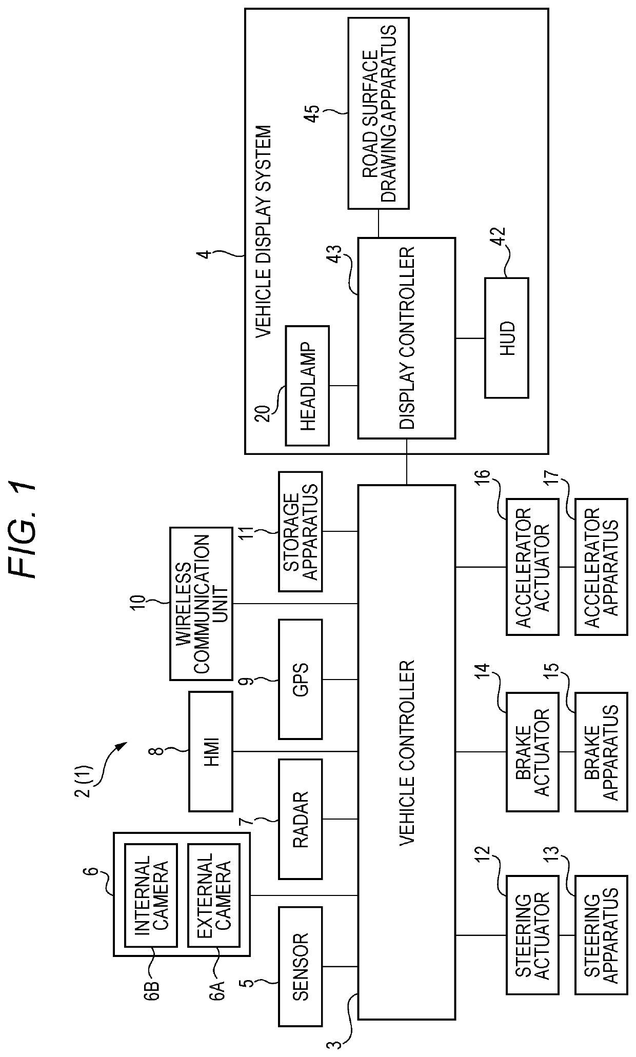
The present patent relates to a head-up display for vehicles that reduces discomfort for the occupants and reduces the processing load on image generation. The display system allows the occupant to easily recognize the displayed light pattern and image. Additionally, the display prevents heat damage due to external light without degrading the quality of the displayed image. Overall, the technical effects of this patent are improved usability and ease of recognition for the occupants of the vehicle.

Problems solved by technology

Specifically, in the manual driving mode, the traveling of the vehicle is controlled according to an operation of the driver (a steering operation, a brake operation, and an accelerator operation), and the vehicle system does not autonomously perform the steering control, the brake control, and the accelerator control.
When external light such as sunlight enters an inside of the head-up display, the external light is focused by a display device and causes a local temperature rise, which may lead to disturbance of image display or heat damage to the display device.
However, in Patent Literature 2, a component for preventing the temperature rise of the display device is separately required, which leads to an increase in cost.

Method used


Image

  • Head-up display, vehicle display system, and vehicle display method
  • Head-up display, vehicle display system, and vehicle display method
  • Head-up display, vehicle display system, and vehicle display method

Examples


first embodiment

[0187]Next, an example of control related to generation of a virtual image object using the HUD 42 according to a first embodiment will be described with reference to FIGS. 3 to 7.

first example

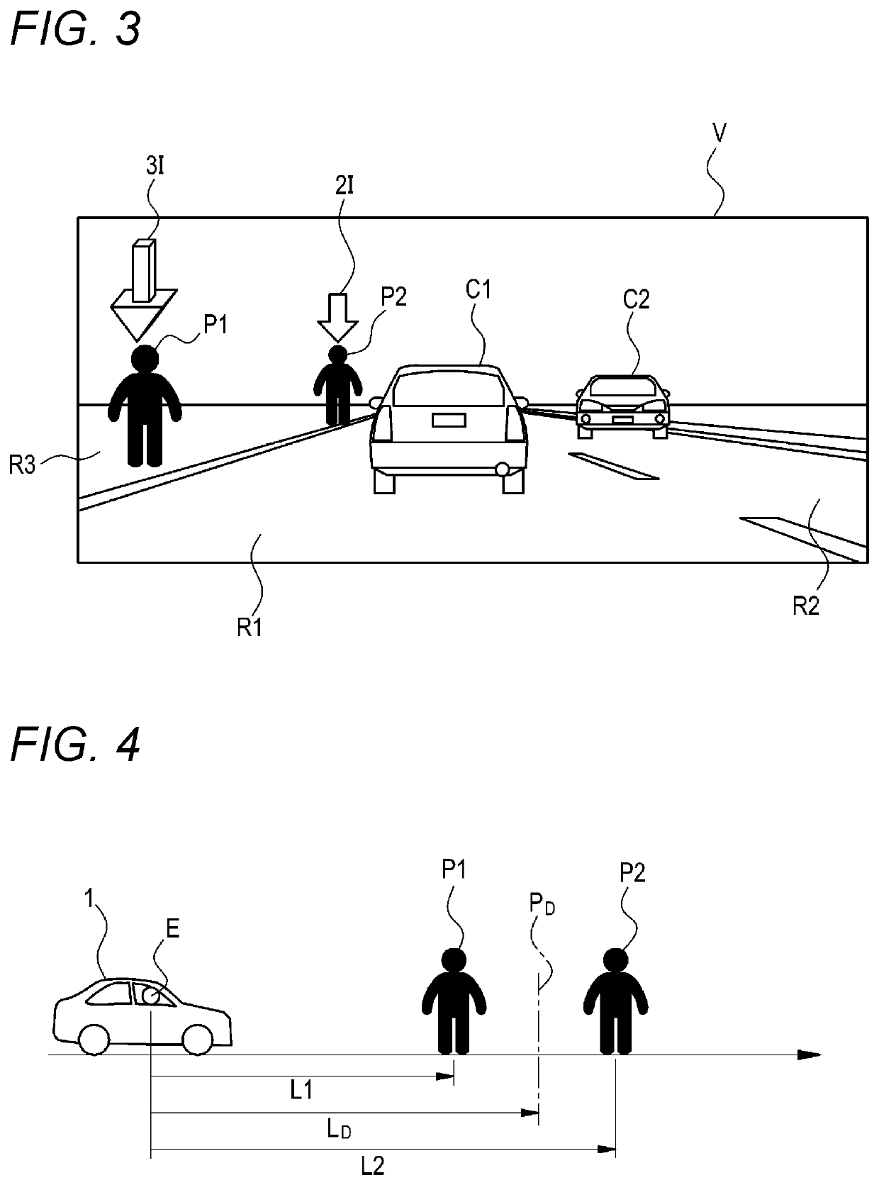
[0188]FIG. 3 is a diagram showing a state where virtual image objects are projected onto a field-of-view region V of the occupant by the HUD 42 in a first example of the first embodiment. FIG. 4 is a schematic diagram showing a relationship between a distance from the viewpoint E to the target object and a threshold.

[0189]In the example shown in FIG. 3, a preceding vehicle C1 that travels in a traveling lane (own vehicle lane) R1 in which the vehicle 1 travels and an oncoming vehicle C2 that travels in an oncoming lane R2 exist in the field-of-view region V of the occupant. Further, pedestrians P1 and P2 exist on a sidewalk R3 on a left side of the traveling lane R1.

[0190]In such a situation, the HUD controller 425 of the HUD 42 controls the image generation unit 424 to generate an image for displaying the virtual image objects in the field-of-view region V in association with positions of the pedestrians P1 and P2 in order to alert the occupant of the vehicle 1 about existence of t...

second example

[0196]FIG. 5 is a diagram showing a state where the virtual image objects are projected onto the field-of-view region V of the occupant by the HUD 42 in a second example of the first embodiment.

[0197]In the example shown in FIG. 5, in the field-of-view region V of the occupant, an obstacle M1 exists on the traveling lane R1 in which the vehicle 1 travels, and an obstacle M2 exists on the oncoming lane R2. Further, a pedestrian P3 exists on the sidewalk R3 on the left side of the traveling lane R1 and a pedestrian P4 exists on the oncoming lane R2.

[0198]In such a situation, the HUD controller 425 may switch a display mode of a virtual image object according to an attribute of each target object regardless of a distance from the viewpoint E to the target object. The attribute of each target object is, for example, importance of each target object. The importance of the target object is, for example, a level of urgency for alerting the occupant of the vehicle 1 to danger. In this examp...


PUM


Abstract

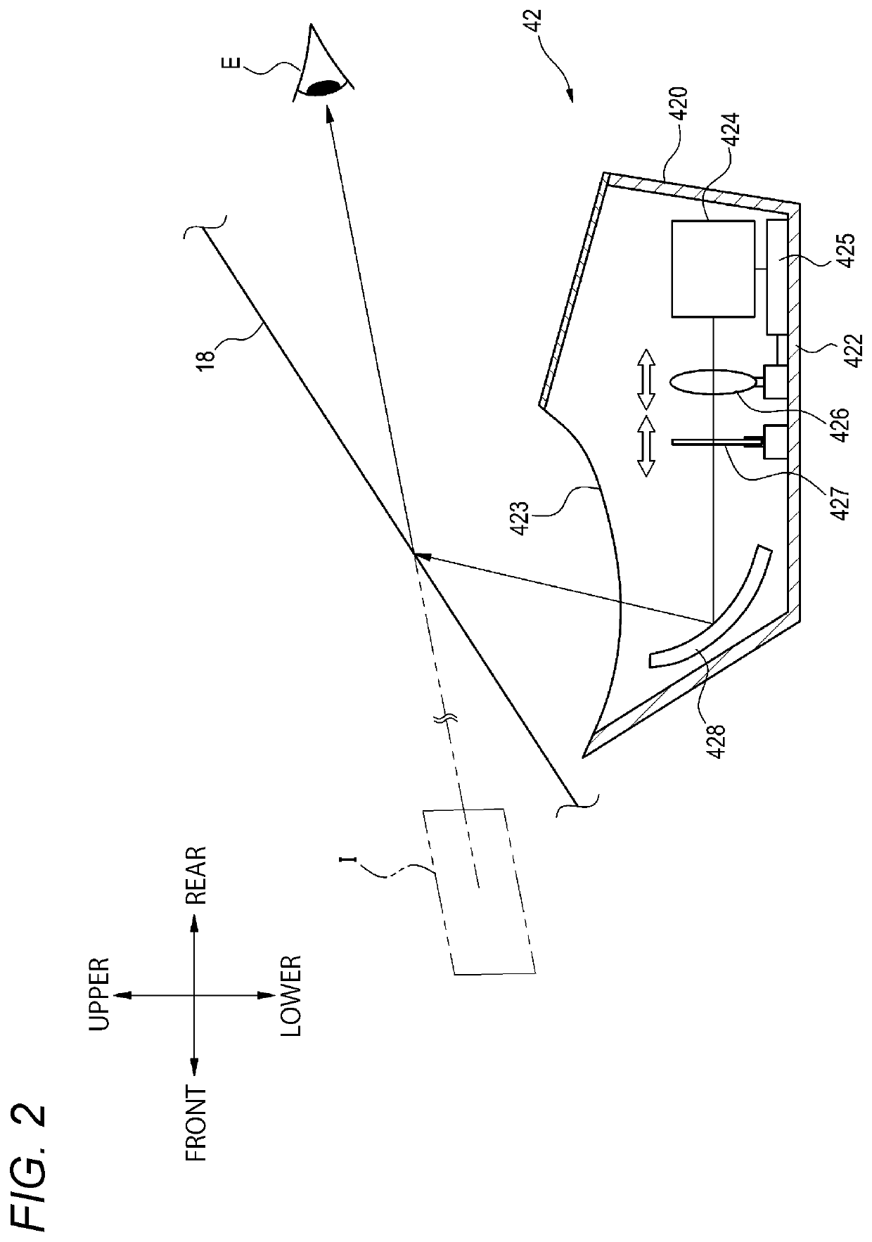
A head-up display is provided in a vehicle and configured to display a predetermined image toward an occupant of the vehicle. The head-up display includes: an image generation unit configured to emit light for generating the predetermined image and to irradiate a windshield or a combiner; and a controller configured to control an operation of the image generation unit. The controller controls the image generation unit to select one of a planar image and a stereoscopic image as a display mode of a virtual image object formed by the predetermined image and visually recognized by the occupant through the windshield or the combiner, according to a predetermined condition.

Description

TECHNICAL FIELD[0001]The present disclosure relates to a head-up display, a vehicle display system, and a vehicle display method.BACKGROUND ART[0002]Currently, research on an autonomous driving technology of an automobile has been actively conducted in various countries, and legislation for enabling a vehicle (hereinafter, the “vehicle” refers to an automobile) to travel on a public road in an autonomous driving mode has been studied in various countries. Here, in the autonomous driving mode, a vehicle system autonomously controls traveling of the vehicle. Specifically, in the autonomous driving mode, the vehicle system autonomously performs at least one of steering control (control of an advancing direction of the vehicle), brake control, and accelerator control (control of vehicle braking, and acceleration or deceleration) based on information indicating a surrounding environment of the vehicle (surrounding environment information) acquired from a sensor such as a camera or a rada...

Claims


Application Information

Patent Timeline
Patent Type & Authority Applications(United States)
IPC IPC(8): G02B27/01G09G3/00H04N13/359B60K35/00
CPCG02B27/0101G09G3/003H04N13/359B60K35/00G09G2380/10G09G2340/12B60K2370/23G09G2320/0666G09G2320/041G02B2027/0141G02B2027/014B60K2370/1529G09G2320/0613B60Q2400/50G01C21/365G09G5/003G09G3/2092G09G5/377G02B2027/0154G02B27/0149G02B2027/0112G02B2027/0138G02B2027/0183G02B2027/0185G02B2027/0187B60K35/23B60K35/211B60K35/28B60K2360/166B60K2360/177B60K2360/179B60K35/29B60K2360/1868B60K2360/31B60K2360/66B60K35/60B60K2360/785B60K2360/23
Inventor MURATA, KOUHEITOYOSHIMA, TAKANOBUSATO, NORIKO
Owner KOITO MFG CO LTD
Learn More