Methods for Direct Printing of Orthodontic and Dental Appliances onto the Teeth of a Patient

a technology for printing orthodontic and dental appliances, applied in the field of three-dimensional printing of orthodontic and dental appliances directly onto the teeth of patients, can solve the problems of slowing down, messy process, and inability to provide a means for feeding direct input from the surface, and achieve the effect of accurate identification

Pending Publication Date: 2022-04-28
LEMCHEN MARC
View PDF47 Cites 0 Cited by
  • Summary
  • Abstract
  • Description
  • Claims
  • Application Information

AI Technical Summary

Benefits of technology

[0011]In yet another embodiment, the method also includes continually monitoring the position of the handheld print head device relative to the surface of the at least one tooth. The print head device may use the scanned anatomy of the tooth and any adjacent teeth or their related structures in order to orientate itself, or alternatively, the print head may recognize temporary anchor devices (TADs) or other appliances to accurately identify its own position and angle relative to the surface of the at least one tooth or patient.

Problems solved by technology

The handheld printer is however entirely reliant on the skill and judgment of the user and does not provide a means for feeding direct input from the surface to be printed on
This process is time consuming, messy, and can highly unpleasant for the patient.
However, even when an intra oral scanner is used, a skilled dental lab technician must still prepare a handcrafted and unique dental or orthodontic appliance based on the digital impression, thus slowing down and increasing the overall costs of treating a patient while also unintentionally inherently impacting accuracy to some degree.

Method used


Image

  • Methods for Direct Printing of Orthodontic and Dental Appliances onto the Teeth of a Patient
  • Methods for Direct Printing of Orthodontic and Dental Appliances onto the Teeth of a Patient

Examples


Embodiment Construction

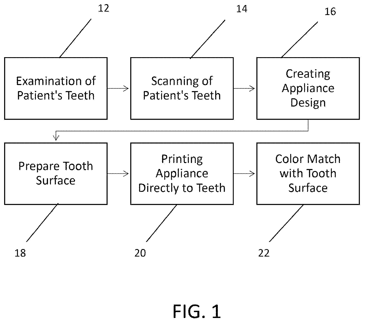
[0026]The method of the current invention employs a dental printer which makes use of one or more three-dimensional printing technologies. Instead of building the object on a “build plate” within a table top printer however, the printing is performed with a print head that is passed multiple times over the surface of a patient's tooth or teeth.

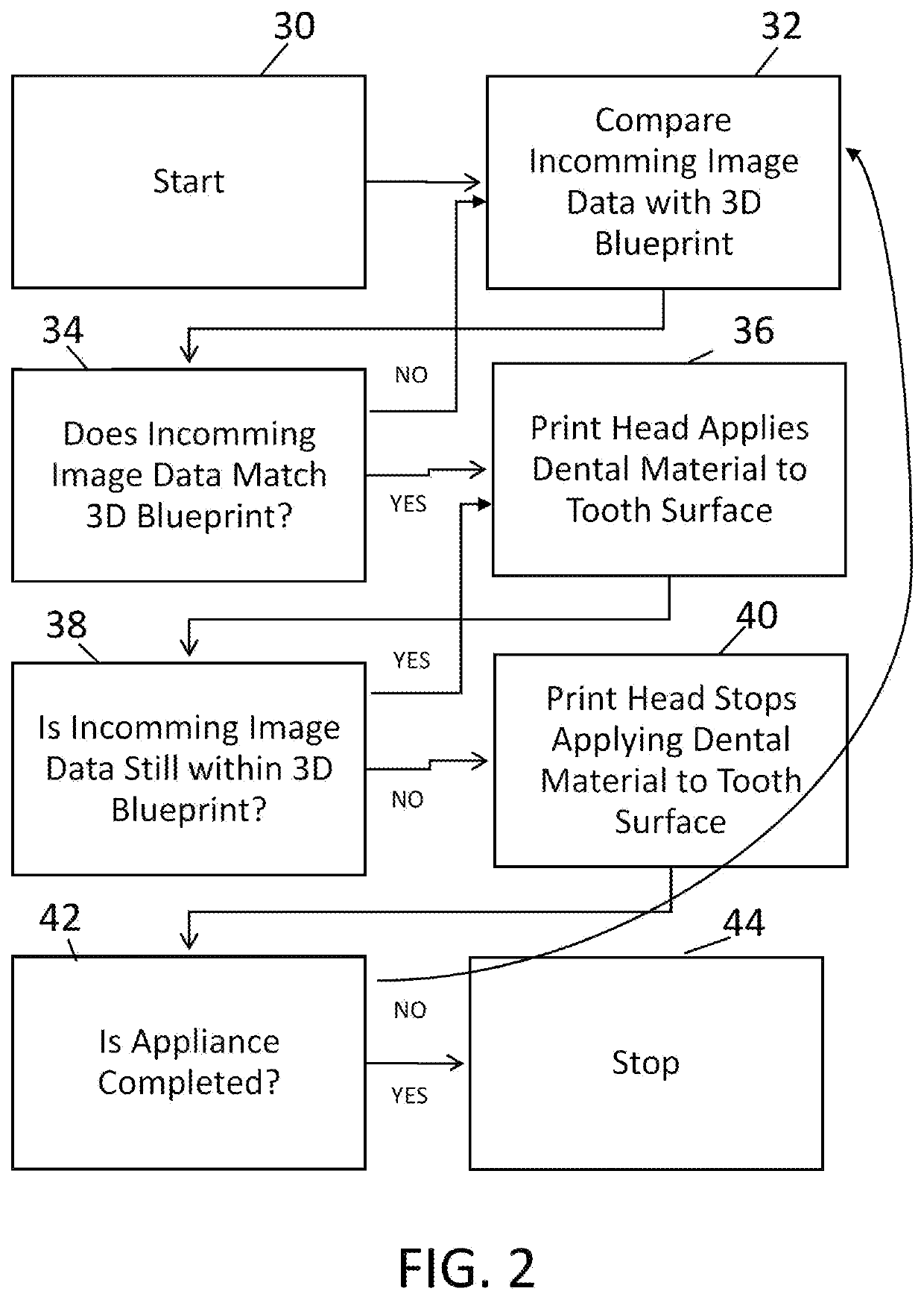
[0027]Specifically, the current invention provides a method for directly printing dental and orthodontic appliances including but not limited to crowns, veneers, and aligner attachments onto the teeth of a patient. The method is performed with a print head which is hand held by a dentist or which may be controlled automatically by a robotic arm or automated system. The print head may itself in one embodiment comprise a conventional dental intra-oral scanner and is communicated with a computer controller and related software which is configured to recognize the anatomy of a tooth or a tooth which was been previously prepared to receive a retain...


PUM

PropertyMeasurementUnit
structureaaaaaaaaaa
coloraaaaaaaaaa
translucencyaaaaaaaaaa

Abstract

A method for directly printing orthodontic and dental appliances on the teeth of a patient. The tooth is scanned with a scanner which is communicated with a computer controller configured to recognize the anatomy of the tooth. The surface of a tooth of the patient is then prepared in order to receive the type of appliance designated for the patient. Using image data from the print head, the computer controller prepares a three-dimensional blueprint or design of an appropriate orthodontic or dental appliance. The computer controller controls the type and amount of material that is distributed through the print head only when the print head passes over the recognized anatomy so as to directly print the corresponding appliance onto the tooth layer by layer as the print head makes successive passes over the surface of the tooth.

Description

RELATED APPLICATIONS[0001]The present application is a non-provisional of U.S. provisional application Ser. No. 63 / 106,252, filed on Oct. 27, 2020 which is incorporated herein by reference in its entirety and to which priority is claimed pursuant to 35 USC 119.BACKGROUNDField of the Technology[0002]The invention relates to methods and apparatus for use in orthodontics and dentistry, in particular three dimensional printing of orthodontic and dental appliances directly onto the teeth of a patient.Description of the Prior Art[0003]Three-dimensional printing of parts and objects for many kinds of applications wherein the part or object was previously machined or molded is well known. For example, everything from picture frames, toys, and trays or racks are frequently printed on increasingly more efficient and cost-effective 3D printers. 3D printers however require a pre-existing or prepared file or blueprint in order print the 3D object. 3D printing has evolved quickly over the last fe...

Claims


Application Information

Patent Timeline
Patent Type & Authority Applications(United States)
IPC IPC(8): A61C5/30A61C9/00A61C7/00A61C13/00A61C7/08A61C5/77A61C7/16A61C13/08B33Y50/00B33Y10/00B33Y80/00
CPCA61C5/30A61C9/0053A61C7/002A61C13/0019A61C7/08B33Y80/00A61C7/16A61C13/082B33Y50/00B33Y10/00A61C5/77G16H40/63G16H50/20B33Y30/00A61C5/20A61C7/14A61C13/0013G16H20/40G16H30/40B33Y50/02B29C64/393B29C64/112G16H15/00
Inventor LEMCHEN, MARC
Owner LEMCHEN MARC
Why Eureka
Try Eureka