Light deflector, light scanning apparatus and image forming apparatus

Pending Publication Date: 2022-05-05
CANON KK
View PDF1 Cites 0 Cited by
  • Summary
  • Abstract
  • Description
  • Claims
  • Application Information

AI Technical Summary

Benefits of technology

The patent aims to reduce the deformation of the surfaces of a rotating mirror used in a light deflector without affecting the quality of the deflection. The technical effect is to improve the performance of the light deflector while maintaining its quietness.

Problems solved by technology

It is difficult to form such a structure by resin molding in consideration of a method for taking out the flange portion from a mold.
Further, there is a possibility that the static surface deformation of the reflecting surfaces occurs due to an axial misalignment of the both holes of the flange portion when the rotation shaft is press-fitted into the flange portion.
However, a wind noise generated when the rotary polygon mirror rotates at high speed may increase.

Method used


Image

  • Light deflector, light scanning apparatus and image forming apparatus
  • Light deflector, light scanning apparatus and image forming apparatus
  • Light deflector, light scanning apparatus and image forming apparatus

Examples


first embodiment

[Image Forming Apparatus]

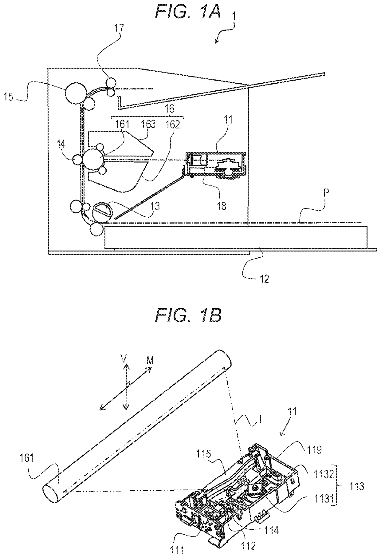
[0021]FIG. 1A is a view showing an image forming apparatus 1 which is an electrophotographic laser printer using a light scanning apparatus 11 of a first embodiment. The light scanning apparatus 11 is installed on an optical bench 18. The optical bench 18 is a portion of a casing of the image forming apparatus 1. The image forming apparatus 1 is provided with a feed unit 12 on which a recording medium (hereinafter referred to as a sheet) P such as paper is placed, a feed roller 13, a transfer roller 14 as a transfer unit, and a fixing device 15 as a fixing unit. Further, in the image forming apparatus 1, an image forming portion 16 is disposed at a position opposite to the transfer roller 14 with respect to a conveying path of the sheet P. The image forming portion 16 is a process cartridge detachably attached to a main body of the image forming apparatus 1. The image forming portion 16 includes a photosensitive drum 161 which is an image bearing member, and...

second embodiment

[Rotary Polygon Mirror]

[0038]FIG. 5 shows a configuration of a light deflector 413 of the second embodiment. A rotary polygon mirror 4131 of the second embodiment has a plurality of reflecting surfaces 423 (423a, 423b). As shown in FIG. 5, the rotary polygon mirror 4131 of the second embodiment has a protrusion 412 and a fitting portion 411 disposed on the + (plus) side in the Z direction. The protrusion 412 is provided on a surface opposite to the circuit board 23 out of two surfaces orthogonal to the rotational axis RA of the rotary polygon mirror 4131. The fitting portion 411 is fitted to the insertion portion 223a of the flange portion 223. The insertion portion 223a is protruded from the surface opposite to the circuit board 23 out of the two surfaces orthogonal to the rotational axis RA of the rotary polygon mirror 4131. Other configurations are the same as those of the first embodiment, and description thereof will be omitted.

[0039]The positioning of the rotary polygon mirror...

third embodiment

[Rotary Polygon Mirror]

[0043]FIG. 7 shows a configuration of a light deflector 513 of the third embodiment. The rotary polygon mirror 5131 of the third embodiment has a plurality of reflecting surfaces 523 (523a, 523b). The rotary polygon mirror 5131 of the third embodiment is supported in the Z direction by a support portion 6231 of a flange portion 623. A fitting portion 511 is fitted to the shaft 21. A protrusion 512 is provided on a surface opposite to the circuit board 23 out of two surfaces orthogonal to the rotational axis direction of the rotary polygon mirror 5131. An insertion portion 623a of the flange portion 623 is provided on the circuit board 23 side from the fitting portion 511 in the rotational axis direction. Other configurations are the same as those of the second embodiment, and description thereof will be omitted.

[0044]In the configuration described above, the shaft 21 and the flange portion 623 are fixed by the shrinkage fitting. A portion fixed by the shrinkag...


PUM


Abstract

A light deflector includes a rotary polygon mirror and a motor to rotate the rotary polygon mirror. The rotary polygon mirror includes reflecting surfaces to reflect light emitted from a light source and a hole portion provided in a rotational axis direction. The motor includes a shaft portion in the hole portion and a support member supporting the rotary polygon mirror. The support member is fixed to, and coaxial with, the shaft portion, and includes an insertion portion in the hole portion. The rotary polygon mirror includes a protruded portion near the hole portion and protruding from at least one reflecting surface orthogonal to the rotational axis direction. The protruded portion includes a fitting portion fitted to the shaft portion or the support member and in which a portion continued from a hole portion surface is protruded toward the rotation center more than the surface forming the hole portion.

Description

BACKGROUND OF THE DISCLOSUREField of the Disclosure[0001]The present disclosure relates to a light deflector, a light scanning apparatus and an image forming apparatus, and relates to an image forming apparatus such as a copying machine, a printer and a facsimile.Description of the Related Art[0002]A light deflector mounted with a rotary polygon mirror formed by cutting a metal material such as aluminum with high accuracy is used as a light deflector provided in a light scanning apparatus. FIG. 8 is a schematic cross-sectional view showing an internal configuration of a conventional light deflector 913. In the conventional light deflector 913, a rotary polygon mirror 931 having reflecting surfaces 933 is supported by a flange portion 921 which is a support member formed of a metal material, and the flange portion 921 is fitted to the rotary polygon mirror 931 at a fitting portion 911. In order to cut and finish the metallic material such as aluminum serving as a base material of the...

Claims


Application Information

Patent Timeline
IPC IPC(8): G03G15/04G02B26/12
CPCG03G15/04036G02B26/121G03G15/0409
Inventor TANAKA, TAKATOSHITANAKA, YOSHIHIKOMATSUSHITA, NAOKI
Owner CANON KK
Why Eureka
Try Eureka