Switch for MV or HV Traction Line Test Device

a technology of traction line and switch, which is applied in the direction of relays, air break switches, test circuits, etc., can solve the problems of difficult requirements for mv and hv mechanical switches for traction line test devices, large contact points of mv switches, and relatively slow operation of switches, etc., to achieve high voltage rating of switches, reproducible and cheap

Pending Publication Date: 2022-05-05
ABB (SCHWEIZ) AG
View PDF0 Cites 0 Cited by
  • Summary
  • Abstract
  • Description
  • Claims
  • Application Information

AI Technical Summary

Benefits of technology

[0013]In one aspect, the present disclosure provides a new construction of the MV or HV switch having high voltage rating of the switch and providing proper galvanic

Problems solved by technology

Requirements for the MV and HV mechanical switch for traction line test device are challenging.
Typical medium voltage switch is designed in respect to the possibility to the occurrence of relatively large short-circuit currents and electrodynamic forces therefore contacts of the MV switches are large and heavy with relatively large inertia and operation of the switch is relatively slow (>15 ms).
The control of all switching elements (opening and closing) must be done simultaneously with a tolerance of typically less than a millisecond, since the total voltage across the switch cascade would otherwise unevenly distributed to their individual elements and it could lead to overvoltage of individual semiconductor switching elements and t

Method used


Image

  • Switch for MV or HV Traction Line Test Device
  • Switch for MV or HV Traction Line Test Device

Examples


Embodiment Construction

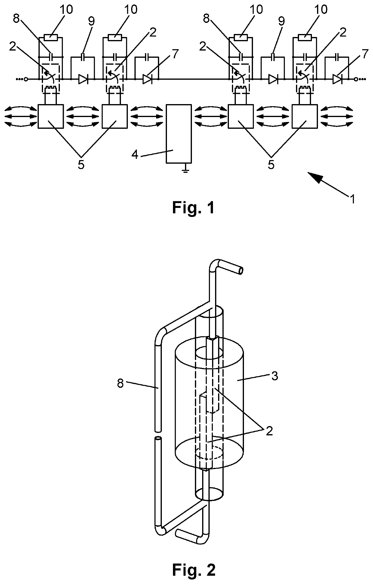
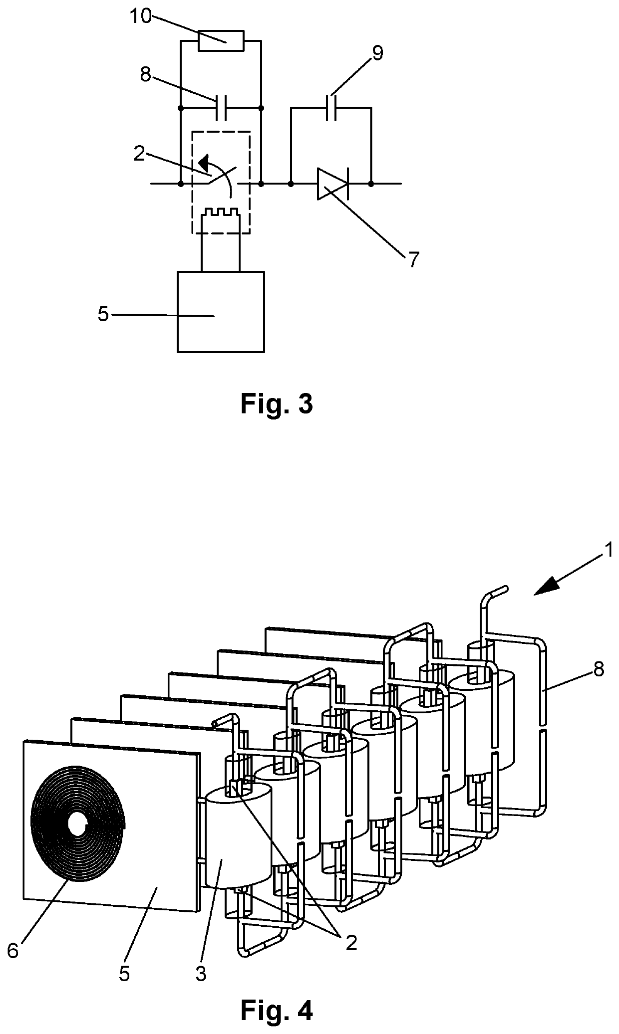
[0036]A proposed switch 1 for a medium or high voltage traction line testing device is shown in FIG. 1, and additional views and alternative embodiments are shown in FIGS. 2-4. The switch 1 comprises a plurality of normally-opened pairs of contacts 2, in the form of vacuum reed relays, connected in series, wherein each pair of contacts 2 is equipped with a separate control coil 3. Dimensions of the pairs of contacts 2 is limited in order to reduce its inertia. Individual pair of contacts 2 close when the respective control coil 3 is supplied.

[0037]The switch 1 comprises also a wireless power transfer supply module 4, which is on ground potential and is used for supplying cascaded wireless power transfer receivers 5. Wireless power transfer supply module 4 is in the form of a transmitting board and comprises a transmitting coil, a high frequency inverter, and a microcontroller. High frequency inverter works with frequency in range 100-300 kHz. The inverter is responsible for the exci...


PUM


Abstract

A switch for a medium or high voltage traction line testing device includes a plurality of normally-opened pairs of contacts connected in series, wherein each pair of contacts is equipped with a separate control coil. The switch further comprises a wireless power transfer supply module being on ground potential for supplying cascaded wireless power transfer receivers comprising the transmitting coil, high frequency inverter and microcontroller, a plurality of cascaded wireless power transfer receivers for supplying control coil of pairs of contacts. Each of the wireless power transfer receivers is referenced to the floating potential and comprises a receiving coil. Each of the control coils is connected to one of the wireless power transfer receivers. The receiving coils of the wireless power transfer receivers are magnetically coupled, and a wireless power transfer supply module is located in the middle of the cascaded wireless power transfer receivers.

Description

CROSS-REFERENCE TO RELATED APPLICATIONS[0001]This patent application claims priority to International Patent Application No. PCT / EP2020 / 070091, filed on Jul. 16, 2020, and European Patent Application No. 19187143.3, filed Jul. 18, 2019, each of which is incorporated herein in its entirety by reference.FIELD OF THE DISCLOSURE[0002]The present disclosure generally relates to a switch for MV or HV traction line test device comprising multiple pairs of contacts connected in series and controlled by separated multiple coils. In one embodiment, the switch is able to reclose in a millisecond range and can operate in medium or high voltage systems which are characterized with high load impedance. Exemplary applications of the switch are generation of short voltage pulses to the high impedance load or providing temporary galvanic insulation between the voltage sensor and the medium voltage source.BACKGROUND OF THE INVENTION[0003]Requirements for the MV and HV mechanical switch for traction l...

Claims


Application Information

Patent Timeline
IPC IPC(8): H01H33/66H01H33/42H01H33/28
CPCH01H33/66H01H33/28H01H33/423H01H9/40H01H33/666H01H50/54H01H36/00H02J50/10H02J50/05H01H33/14H01H9/54G01R31/14
Inventor RUSZCZYK, ADAMKOSKA, KRZYSZTOFORAMUS, PIOTR `
Owner ABB (SCHWEIZ) AG
Why Eureka
Try Eureka