
Picture frame comprising a viewing window side and a frame side, picture frame system, connecting element

a picture frame and viewing window technology, applied in the field of picture frames, can solve the problems of only being used on one side of the picture frame, affecting the appearance of the picture to be displayed, and affecting the overall picture, so as to achieve the effect of thicker material and visible connection

Pending Publication Date: 2022-05-12
NINABER
View PDF0 Cites 0 Cited by
  • Summary
  • Abstract
  • Description
  • Claims
  • Application Information

AI Technical Summary

Benefits of technology

The present invention provides a picture frame and system that allows for seamless transition between partial pictures on different frames without interruptions. The frames have edges with complementary parts that help position them correctly. The frame and viewing window section are connected with a temporary bending of the mounting elements, resulting in a click connection between the notches in the viewing window section and assembly elements on the frame section. This ensures the proper positioning of the frame and viewing window section during assembly.

Problems solved by technology

Cutting one picture into several parts and placing them in different frames in order to display the overall picture would cause excessive interruptions in the overall picture because of the space required for the assembly components.
There will be an interruption in the appearance of the picture to be displayed at or near the transition from a picture frame to an adjacent picture frame due to the distance from one part of the photo to the next part of the photo being too great.
As a result, the picture frame can only be used on one side.
Transparency as a property of the plastic causes this plastic to be very rigid and inflexible.
A soft-curing injection moulded plastic with the envisaged surrounding wall thickness of 1 to 3 mm cannot or can hardly be produced as a completely clear plastic because the soft properties are achieved by plasticizers which will cloud the material.
Not only do these assembly options take up space in the viewing plane of the picture, but they also come with separate elements which complicate assembly.
Simple punching devices can only punch a hard material of minor thickness because too much force is required to cut through thicker material.
Existing systems require much space in the viewing plane outside the dimensions of the picture to assemble the front and back together.
In the prior art, in many cases, the assembly elements and the connection mechanism technology are located centrally between the frame parts and therefore require a lot of space in the visible surface.
Altogether, this minimum space is insufficient to use assembly techniques such as nuts and bolts or similar techniques according to the method in the prior art.

Method used


Image

  • Picture frame comprising a viewing window side and a frame side, picture frame system, connecting element
  • Picture frame comprising a viewing window side and a frame side, picture frame system, connecting element
  • Picture frame comprising a viewing window side and a frame side, picture frame system, connecting element

Examples


Embodiment Construction

[0069]The parts of the picture frame and the picture frame assembly shown in the figures have been provided with the following numerals:

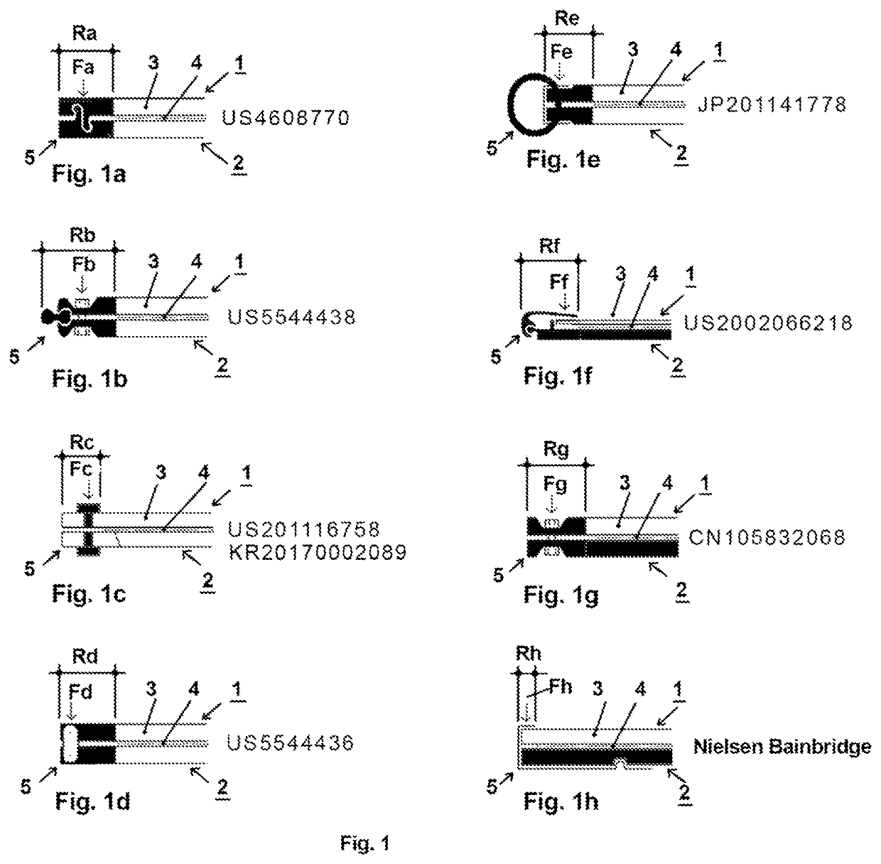
[0070]FIGS. 1A to 1L illustrate known picture frames. The locations where the figures can be found are always indicated next to them. The designation “Nielsen Bainbridge” refers to a commercially available existing model.

[0071]The picture frames comprise a viewing window side 1 provided with a viewing window 3, a frame side 2 and assembly components 5 in order to assemble the viewing window and frame sides together. A photo or picture 4, visible through the viewing window 3, is provided for between the viewing window side 1 and the frame side 2. Note that the fact that one of the sides is referred to as the “viewing window side” does not exclude that the opposite side, the ‘frame side’ is also transparent. In that case, both sides are both the viewing window side and the frame side.

[0072]In FIG. 1A, showing a picture frame known from U.S. Pat. No. 4...


PUM


Abstract

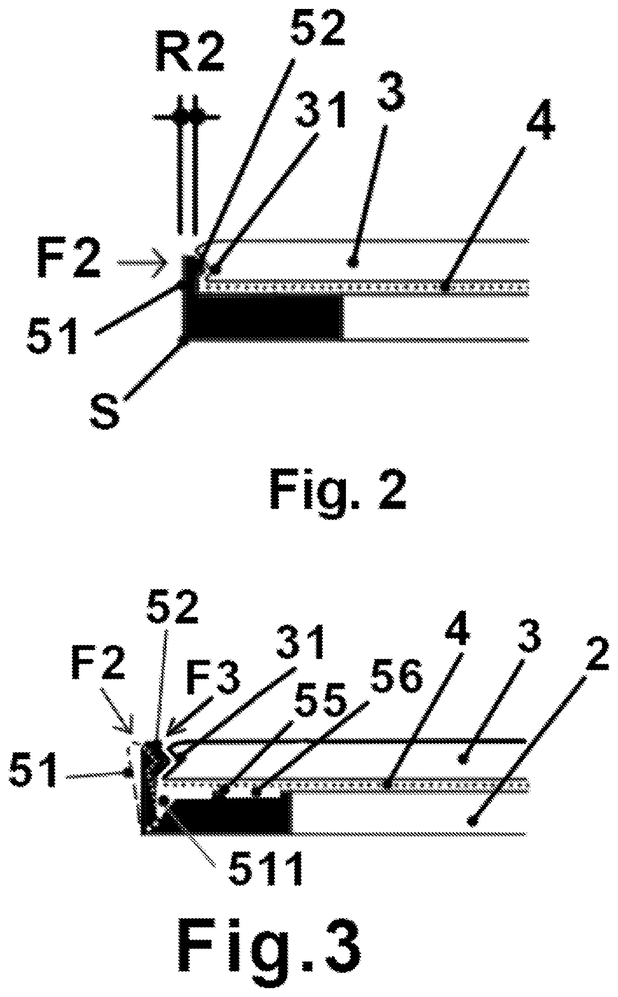
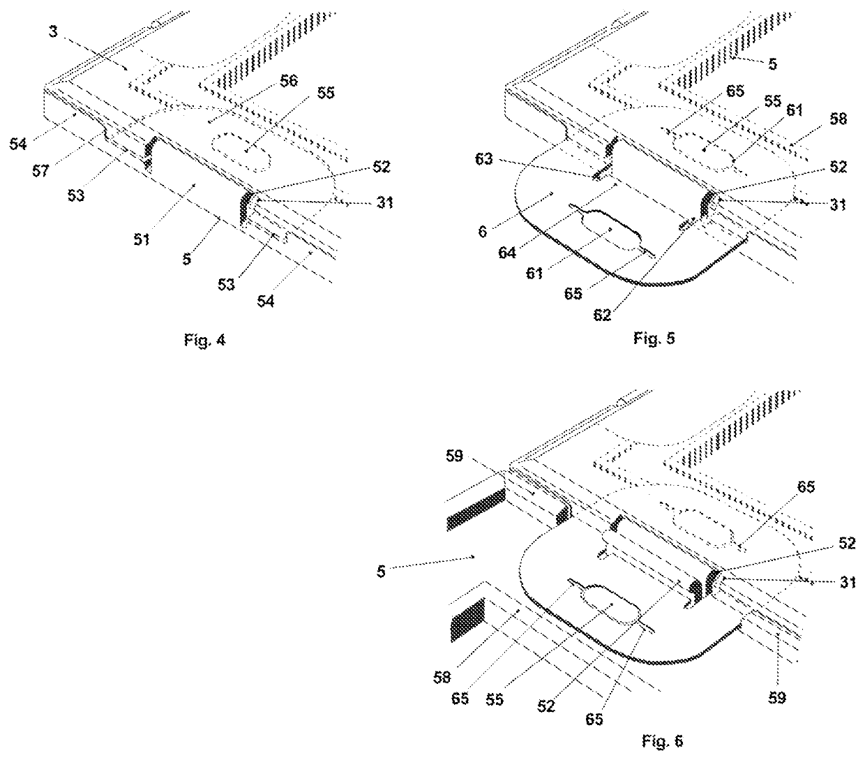
A picture frame comprises a viewing window side (1) and a frame side (2). There is a interstice between the viewing window and the frame side. The viewing window and frame sides comprise assembly components (5) in order to assemble the viewing window and frame sides together. An assembly component on the frame side comprises a flexible protruding clamping part (51) provided with a clamping section (52) on a side facing the viewing window (3) and the viewing window (3) is provided with a complementary clamping section (31) at an edge of the viewing window (3) with the complementary clamping sections (52, 31) fitting into each other and with, when assembled, the protruding clamping parts (51) on the frame side exert a clamping force (F2) on the viewing window with the direction of the clamping force (F2) being mainly in the flat plane of the viewing window.

Description

BACKGROUND AND SUMMARY OF THE INVENTION[0001]The invention concerns a picture frame comprising a viewing window side and a frame side, with the viewing window side comprising a transparent window and with there being an interstice between the transparent window and the frame side for placing a flat object, i.e. a photo or picture, which can be visibly positioned to either side, and with the viewing window and frame sides comprising assembly components for mounting the viewing window and frame sides onto each other and thereby enclosing the flat object.[0002]The invention also concerns a picture frame system comprising at least two picture frames forming an arrangement of picture frames which can be connected together by means of connecting elements.[0003]The invention also concerns a connecting element for connecting picture frames together.[0004]Frames comprising a viewing window side and a frame side which can be mounted onto each other, with a picture being visible through the tr...

Claims


Application Information

Patent Timeline
IPC IPC(8): A47G1/06
CPCA47G1/065A47G1/0611
Inventor NINABER, JOHANNES HENDRIKUS
Owner NINABER
Learn More