
Compactor and diverter for return items in a dispensing system

a dispensing system and compacting technology, applied in the field of compacting apparatus, can solve the problems of inability to maintain, inability to accept and replace scrubs, and inability to meet the needs of cleaning, and achieve the effect of increasing the effective storage capacity of the return unit or cabin

Active Publication Date: 2022-05-12
CINTAS CORP SERVICES INC
View PDF1 Cites 0 Cited by
  • Summary
  • Abstract
  • Description
  • Claims
  • Application Information

AI Technical Summary

Benefits of technology

The returns cabinet has a controller that helps move the compactor. This allows garments to be spread out and compacted, which makes it easier to store them. The compactor helps to make to apply pressure to the soiled garments, making them easier to dispose of. Overall, this makes the storage unit more effective.

Problems solved by technology

Soiled scrubs are collected for laundering and subsequent reuse, but scrubs must be periodically replaced due to wear and tear encountered in normal use as well as the effects of repeated launderings using the high temperatures and detergents required to clean and sterilize the soiled scrubs.
These and other improper uses of scrubs contribute to an unacceptable shrinkage in the inventory of scrubs maintained by the institution for use by authorized persons.
Although this approach can alleviate the problems mentioned above, it is expensive to maintain.
The direct and indirect labor costs of that staffing add significantly to the overall cost of maintaining an adequate inventory of scrubs.
Regarding the collection of soiled scrubs, manual collection suffers the disadvantage of human error, forgetfulness, and the like.
Adapting the garment receiving apparatus of the unit shown in U.S. Pat. Nos. 5,713,270 and 5,829,349 into a compact unit presents difficulties, because a compactor by which the garments are compacted according to the '270 and '349 patents is shaped as a sweeping, vertical sheet metal device.
Thus, the effective volume of clothing that the collection area can hold is limited by the limited contact area of the edge of the device.

Method used


Image

  • Compactor and diverter for return items in a dispensing system
  • Compactor and diverter for return items in a dispensing system
  • Compactor and diverter for return items in a dispensing system

Examples


Embodiment Construction

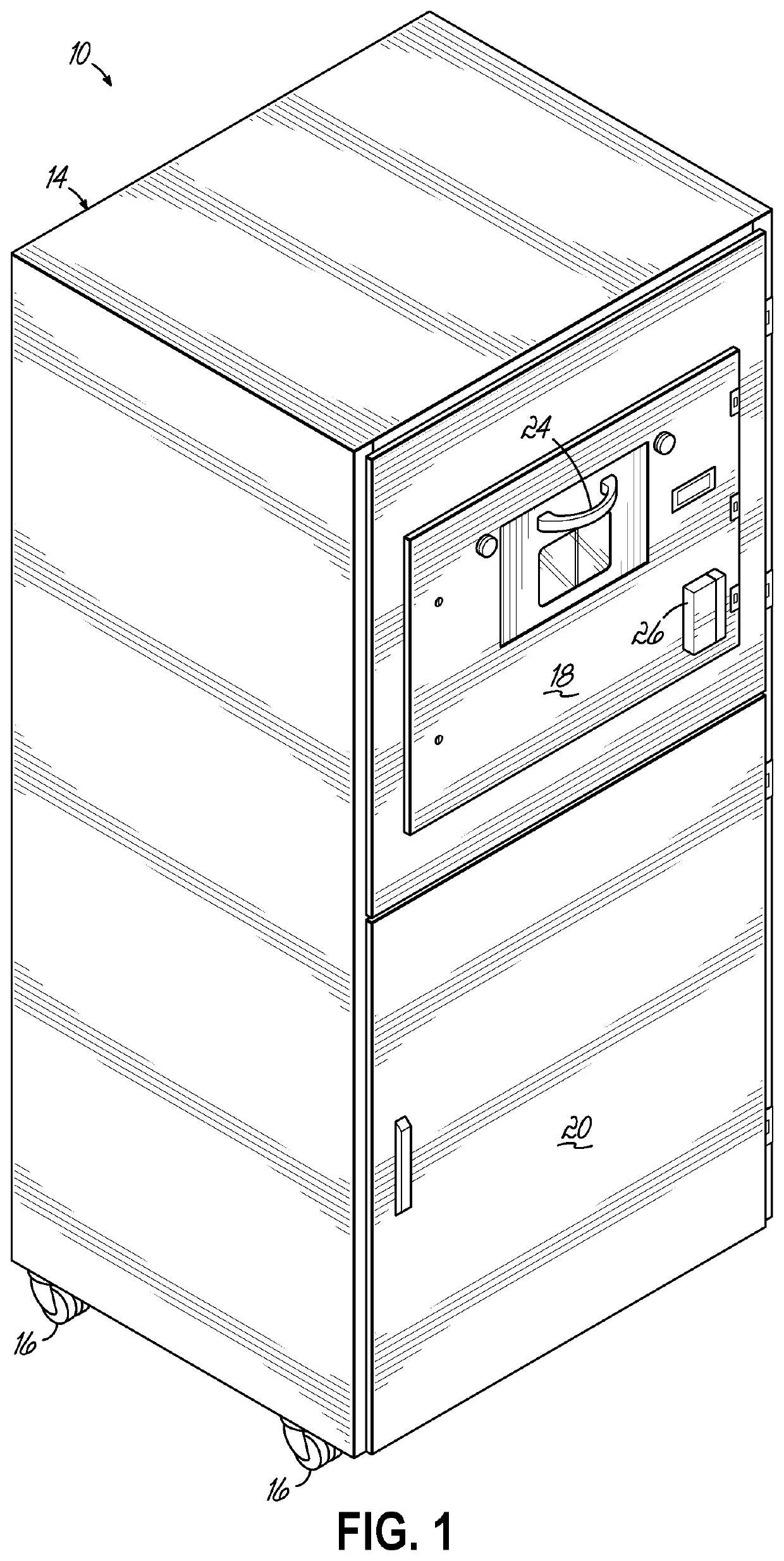
[0027]Referring to FIG. 1, one embodiment of a returns cabinet 10 for use in conjunction with a dispensing system according to this invention is shown. The dispensing system may be according to that which is disclosed in U.S. Pat. No. 7,474,938 or another compatible or appropriate dispensing system. The returns cabinet 10 according to various embodiments of this invention could be used to receive used, worn, soiled or other items 12 which are reusable, particularly textile materials such as scrubs used in a hospital environment. The returns cabinet 10 receives the items or scrubs 12 from a user and credits the user's account with the return of those items to allow for new or additional items or scrubs 12 to be issued to the particular user.

[0028]The returns cabinet 10 as shown in FIG. 1 includes an outer housing 14 and may be supported on multiple rollers or wheels 16 for convenient movement of the returns cabinet 10, as needed. The returns cabinet 10, as previously stated, may be u...


PUM


Abstract

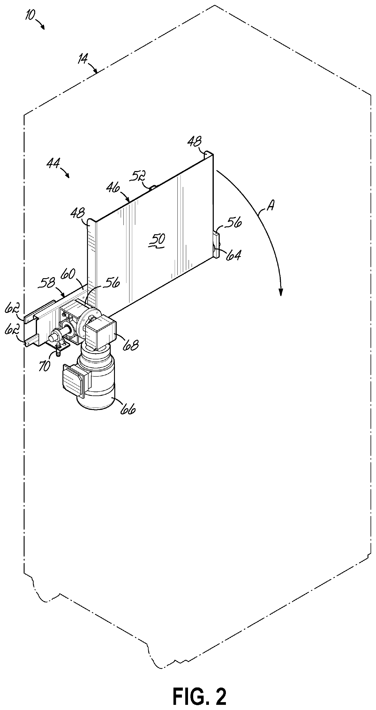
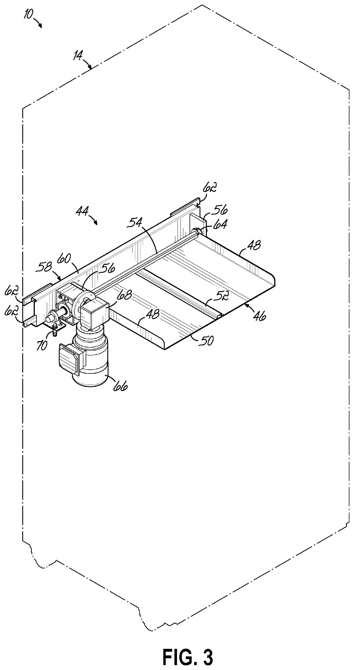
A scrubs returns cabinet for a hospital allows workers to return surgical garment tops and bottoms. A cabinet housing has a loading door leading to a return port through which the customer places the soiled scrub suit after entering customer identification information. The scrubs fall into a collection area and are dispersed by a diverter into the collection area. Additionally, a compacting paddle compacts the accumulating scrubs to utilize more of the collection area and accommodate more dirty scrubs before the collection area needs to be emptied. The scrubs are compressed by the compactor after being dispersed by the diverter.

Description

BACKGROUND OF THE INVENTION[0001]This invention relates to an apparatus for receiving and compacting articles, and more particularly to an apparatus for accepting and directing garments into a compartment and compacting them therein.[0002]Scrub garments are uniforms typically worn by doctors, nurses, and other medical workers in hospital operating rooms or other locations where the workers are likely to be in immediate proximity with patients. These scrub garments are hereafter called “scrubs”. Scrubs provide an easily-changed launderable barrier between the wearer and the patient, helping to prevent the patient from exposure to germs or infectants on the wearer's body or street clothing, and also helping to protect the wearer's body from direct physical contact with a patient.[0003]Scrubs usually are two-piece garments, consisting of a top or shirt and a bottom or pants. The tops and bottoms are stocked in different sizes to accommodate the needs of individual wearers. Scrub jacket...

Claims


Application Information

Patent Timeline
IPC IPC(8): A61B50/37B30B9/30
CPCA61B50/37B30B9/3082B30B9/3003B30B9/3046
Inventor SAVAGE, JOHNBAYLOR, BRETTGALLEGOS, AARONHELGREN, DALESCHROEDER, SCOTT
Owner CINTAS CORP SERVICES INC
Learn More