Electro-static discharge device with integrated capacitance

a technology of integrated capacitance and electrostatic discharge, which is applied in the field of electrostatic discharge devices, can solve the problems of insufficient filtering of common-mode noise, achieve the effect of increasing capacitance, improving the ability of the resulting physical-layer component 400 to filter out common-mode noise, and sufficiently filtering out common-mode nois

Pending Publication Date: 2022-05-19
NXP USA INC
View PDF5 Cites 0 Cited by
  • Summary
  • Abstract
  • Description
  • Claims
  • Application Information

AI Technical Summary

Benefits of technology

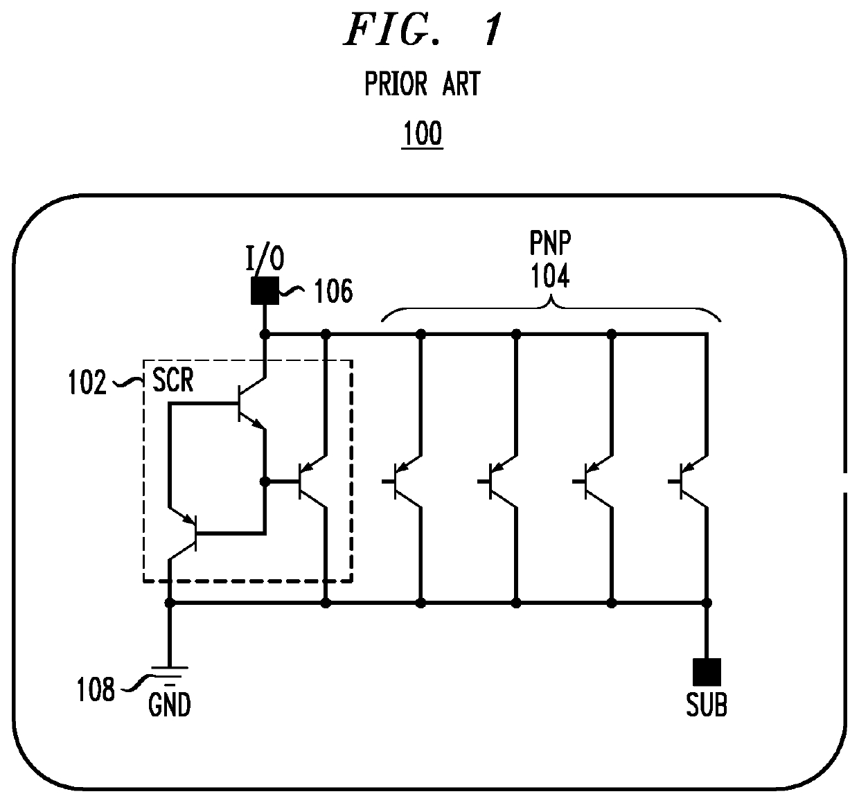
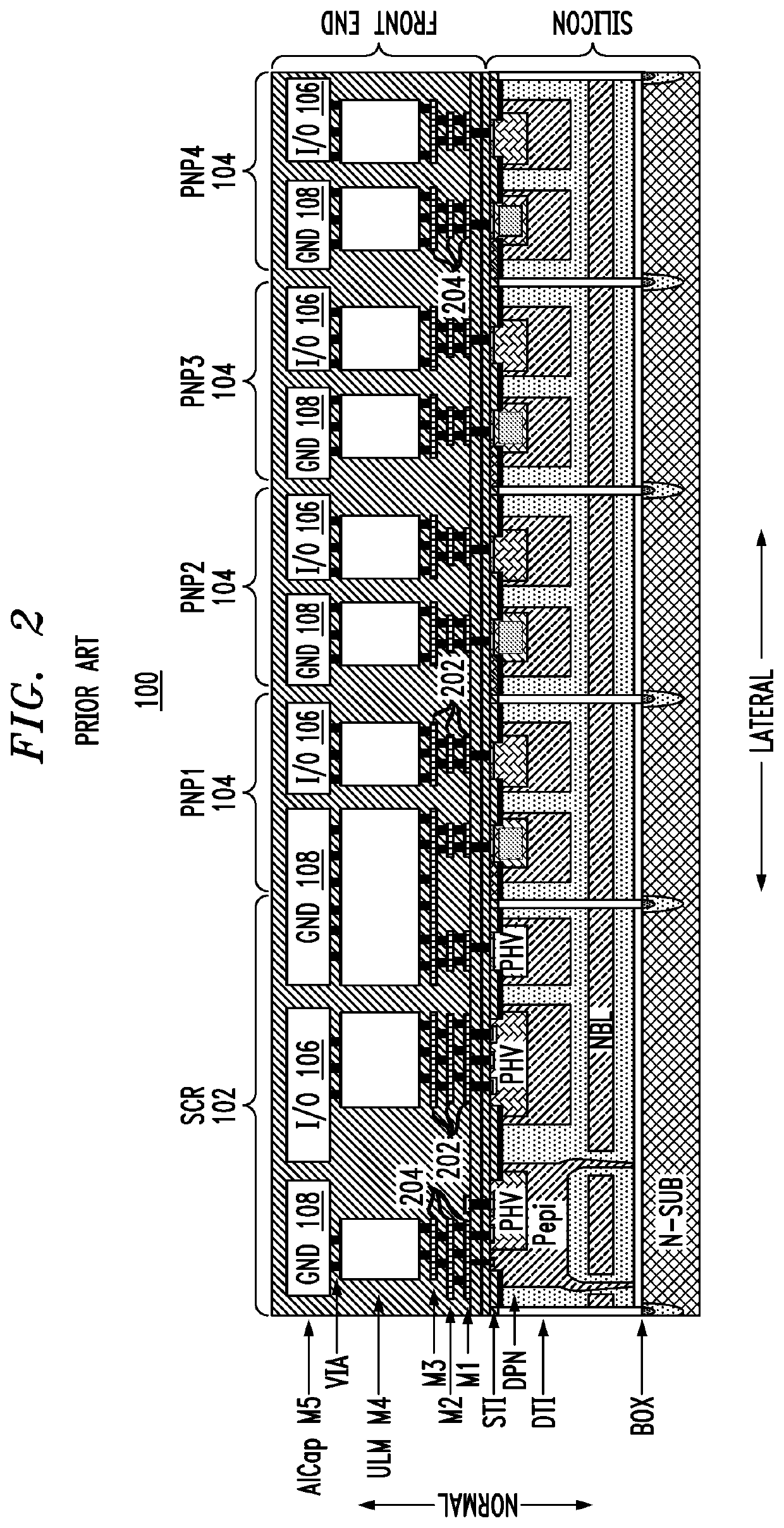
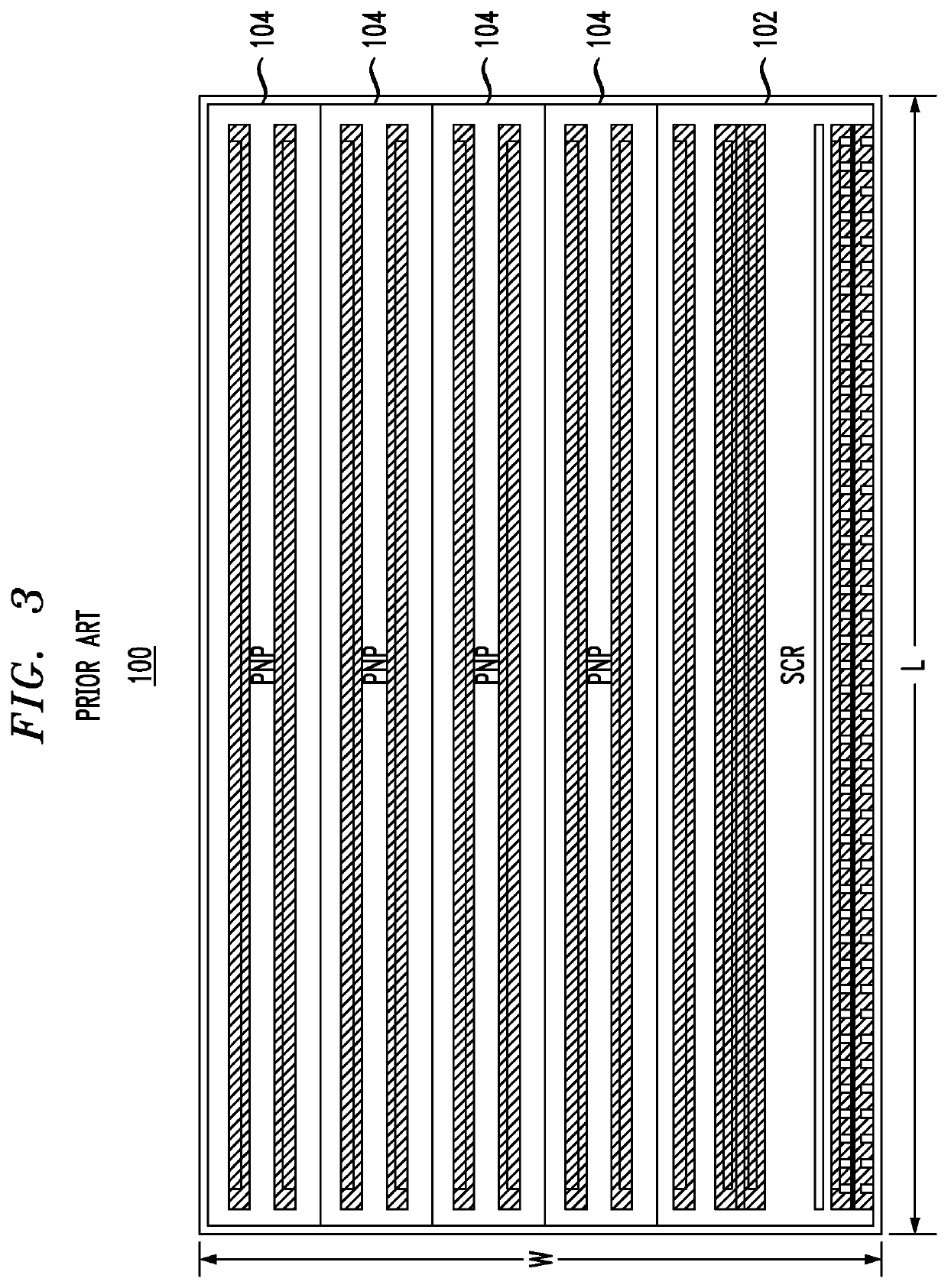
[0009]One of the drawbacks of the conventional CAN physical-layer component 400 of FIG. 4 is its inability to filter out common-mode noise sufficiently when there is significant asymmetry between the differential-signal components on the CAN transmission line. To address this drawback, parallel capacitance can be added to each instance of the ESD device. According to the present disclosure and as described further below, that parallel capacitance is integrated into the front end of the ESD device within its active area by modifying the sizes of at least some of the first-terminal and second-terminal metal features in the metal layers M1-M3 of the ESD device to increase the capacitances both (i) between first-terminal and second-terminal metal features within each metal row (i.e., in the lateral direction) as well as (ii) between first-terminal and second-terminal metal features within adjacent metal rows (i.e., in the normal direction). As a result, additional parallel capacitance is added between the I / O and ground terminals of the ESD device, which additional parallel capacitance improves the ability of the resulting physical-layer component 400 to filter out common-mode noise even in the presence of significant asymmetry between the differential-signal components.

Problems solved by technology

One of the drawbacks of the conventional CAN physical-layer component 400 of FIG. 4 is its inability to filter out common-mode noise sufficiently when there is significant asymmetry between the differential-signal components on the CAN transmission line.

Method used


Image

  • Electro-static discharge device with integrated capacitance
  • Electro-static discharge device with integrated capacitance
  • Electro-static discharge device with integrated capacitance

Examples


Embodiment Construction

[0029]Detailed illustrative embodiments of the present disclosure are disclosed herein. However, specific structural and functional details disclosed herein are merely representative for purposes of describing example embodiments of the present disclosure. The present disclosure may be embodied in many alternate forms and should not be construed as limited to only the embodiments set forth herein. Further, the terminology used herein is for the purpose of describing particular embodiments only and is not intended to be limiting of example embodiments of the disclosure.

[0030]As used herein, the singular forms “a,”“an,” and “the,” are intended to include the plural forms as well, unless the context clearly indicates otherwise. It further will be understood that the terms “comprises,”“comprising,”“contains,”“containing,”“includes,” and / or “including,” specify the presence of stated features, steps, or components, but do not preclude the presence or addition of one or more other feature...


PUM

PropertyMeasurementUnit
capacitanceaaaaaaaaaa
physicalaaaaaaaaaa
voltageaaaaaaaaaa

Abstract

An integrated electro-static discharge (ESD) device has a set of metal layers. Each metal layer in the set has one or more first-terminal metal features interleaved with one or more second-terminal metal features in a lateral direction, and at least one first-terminal metal feature in a metal layer of the set overlaps in a normal direction at least one second-terminal metal feature in an adjacent metal layer of the set. By overlapping metal features in the normal direction, capacitance can be added to the ESD device, which improves its operating characteristics, without increasing the layout size of the ESD device.

Description

BACKGROUNDField of the Disclosure[0001]The present disclosure relates to electronics and, more specifically but not exclusively, to the use of electro-static discharge (ESD) devices to protect electronics, such as physical-layer components, from high-voltage transients.Description of the Related Art[0002]This section introduces aspects that may help facilitate a better understanding of the disclosure. Accordingly, the statements of this section are to be read in this light and are not to be understood as admissions about what is prior art or what is not prior art.[0003]It is known to use an electro-static discharge (ESD) device in a physical-layer component to protect other electronics from damage due to high-voltage transients that may appear on a transmission line connected to an input / output (I / O) port of such a physical-layer component. In operation, an ESD device provides a path to shunt such high voltages to ground, thereby protecting other circuitry of the physical-layer comp...

Claims


Application Information

Patent Timeline
Patent Type & Authority Applications(United States)
IPC IPC(8): H02H9/04H01L27/02
CPCH02H9/044H01L27/0248H02H9/046H01L27/0288H01L27/02H02H9/04
Inventor STEFANOV, EVGUENIY NIKOLOVABOUDA, PASCAL KAMEL
Owner NXP USA INC
Why Eureka
Try Eureka