Magnetic bearing device having a toroidal design

a magnetic bearing and toroidal technology, applied in the direction of bearings, shafts and bearings, rotary machine parts, etc., can solve the problems of reducing the service life of the rotor, increasing the cost and size, and comparatively high magnetic resistan

Pending Publication Date: 2022-05-26
MECOS
View PDF7 Cites 0 Cited by
  • Summary
  • Abstract
  • Description
  • Claims
  • Application Information

AI Technical Summary

Benefits of technology

[0013]It is an object of the present invention to provide a magnetic bearing device for controlling at least radial displacements of a rotor that can be constructed in a compact and cost-efficient manner, making it particularly well-suited for small rotors.

Problems solved by technology

This traditional design is not optimally suited for rotors that have small diameter (e.g., a diameter below a few centimeters).
With small-diameter rotors, the length of the air gap between the stator teeth and the rotor becomes comparatively large in relation to the rotor diameter, leading to a comparatively high magnetic reluctance.
This adds to both cost and size.
This design requires considerable space, and the bearing forces that can be generated in the homopolar part are rather limited.
This design is relatively complex.
Applicability of this design is limited to extremely short, ring-shaped rotors.

Method used


Image

  • Magnetic bearing device having a toroidal design
  • Magnetic bearing device having a toroidal design
  • Magnetic bearing device having a toroidal design

Examples


first embodiment

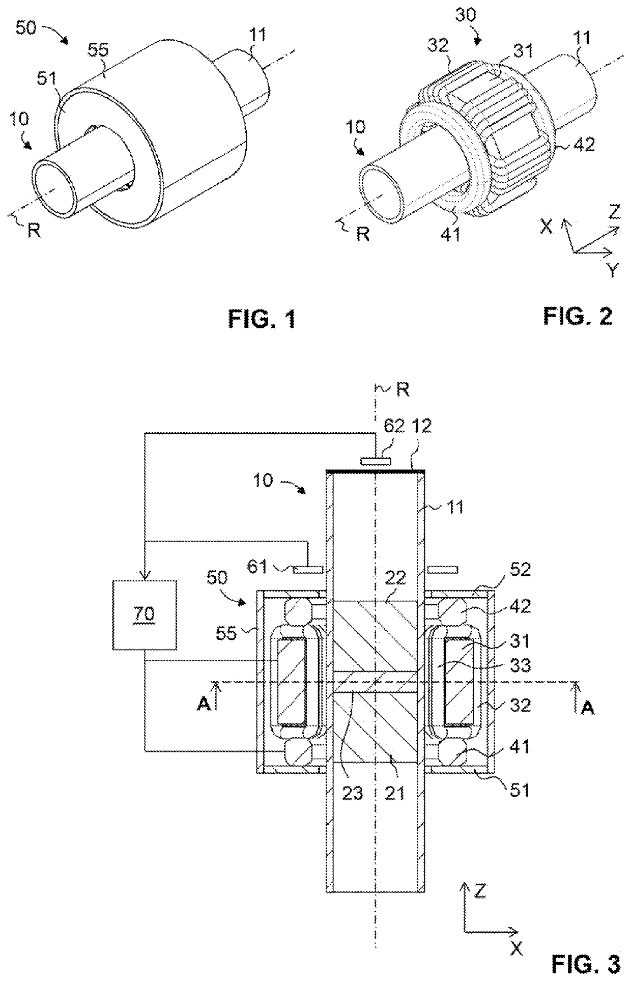
[0055]In FIGS. 1 to 3, a magnetic bearing device according to the present invention is illustrated. FIG. 1 shows the magnetic bearing device including its housing, while FIG. 2 shows the device without the housing. In FIG. 3, additional components of the magnetic bearing device are illustrated, which are absent from FIGS. 1 and 2.

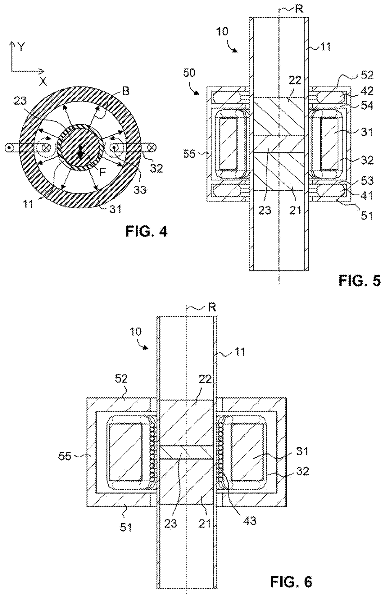
[0056]A rotor 10 comprises a hollow tube 11 made of a non-magnetic material like austenitic steel, titanium, aluminum or fiber-reinforced plastics. In order to minimize losses by eddy currents, it may be advantageous to manufacture hollow tube 11 from a material having high electrical resistivity. Inside the hollow tube 11, a first permanent magnet 21 and a second permanent magnet 22 are held. Both permanent magnets 21, 22 are axially magnetized. They have opposite polarities. Axially between and immediately adjacent to the permanent magnets 21, 22, a magnetic guide disk 23 is held. The magnetic guide disk 23 is made of a magnetically soft material, i.e., o...

fifth embodiment

[0077]a magnetic bearing device is illustrated in FIGS. 9 and 10. In this embodiment, two ring-shaped magnetic cores 31A, 31B are present, and a plurality of radial magnetic bearing windings 32A, 32B in toroidal configuration are provided on each of the ring-shaped magnetic cores 31A, 31B. Two azimuthally wound, cylindrical axial bearing windings 43A, 43B are provided, each of these axial bearing windings being arranged in the radial gap between the rotor 10 and one set of radial bearing windings 32A, 32B, respectively. Only a single permanent magnet 24 is provided. The permanent magnet 24 is magnetized along the rotation axis R. On each axial end of the permanent magnet 24, an optional magnetic guide disk 25, 26 is provided.

[0078]Radial forces are generated in a similar manner as described above for the first embodiment. For instance, radial bearing windings 32A, 32B arranged on the same ring-shaped magnetic core 31A, 31B, but on diametrically opposite radial sides of the rotor 10 ...


PUM


Abstract

A magnetic bearing device comprises a stator (30) and a rotor (10) supported in the stator for rotation around a rotation axis (R). The rotor comprises at least one permanent magnet (21, 22) that is magnetized along the rotation axis. The stator comprises at least one closed magnetic core (31) that surrounds the rotor (10) and at least one radial bearing winding (32) arranged on the closed magnetic core (31) in a toroidal configuration. The at least one radial bearing winding is arranged to interact with a permanent magnetic field generated by the at least one permanent magnet to obtain a radial bearing force when current is supplied to the at least one radial bearing winding.

Description

TECHNICAL FIELD[0001]The present invention relates to a magnetic bearing device comprising a stator and a rotor supported in the stator for rotation around a rotation axis.PRIOR ART[0002]Active magnetic bearings are often used to support moving parts without physical contact. If the moving part is a rotor supported for rotation around a rotation axis, it is known to control both radial and axial displacements of the rotor by active magnetic bearings.[0003]In a commonly employed design, an active radial magnetic bearing comprises a magnetically soft stator core having structures that extend radially inwards, commonly called “teeth”. Each stator tooth forms an air gap with the rotor, which also is magnetically soft. Stator windings are provided on the stator teeth or between adjacent stator teeth. A current in a stator winding causes a magnetic flux through the stator core, the associated stator teeth and the rotor, which gives rise to an attractive reluctance force between the stator...

Claims


Application Information

Patent Timeline
Patent Type & Authority Applications(United States)
IPC IPC(8): F16C32/04
CPCF16C32/0474F16C32/0446F16C32/0451F16C32/0461F16C32/0468F16C32/048F16C32/0485F16C32/0489F16C2300/12
Inventor BÜHLER, PHILIPP
Owner MECOS
Why Eureka
Try Eureka