Rear-mounted deep hole machining on-line detection and deviating correction device

a technology of deviating correction and deep hole machining, which is applied in the field of rear-mounted deep hole machining online detection and deviating correction devices, can solve the problems of poor rigidity, low strength, and impingement of the straightness of the deep hole, and achieves good straightness and position accuracy, compact footprint, and avoid the effect of high temperature generated during the machining process

Active Publication Date: 2017-05-18
ZHONGBEI UNIV
View PDF6 Cites 0 Cited by
  • Summary
  • Abstract
  • Description
  • Claims
  • Application Information

AI Technical Summary

Benefits of technology

[0015]The disclosure provides advantages of ensuring good straightness and position accuracy of the machined deep hole. Specifically, the advantages includes: Firstly, the laser transmitter and the photosensitive sensor are positioned on the outer frame, such that high temperature generated during the machining process is avoided from affecting the laser transmitter and the sensor. If one of the laser transmitter and the photosensitive sensor were to be positioned within the hole, it would be difficult to achieve the detection effect due to the generated high temperature. The disclosure takes full advantage of the parallel reflection of the laser beam produced by the pyramid prism to achieve the aforementioned effect. Secondly, by means of observing the graphics displayed on the computer, the position variation of the deep hole cutter is detected on line and thus the working conditions of the workpiece rotation and the deep cutter feeding during the deep hole machining process are obtained in time. Since the position variation of the deep hole cutter indirectly reflects the hole quality, the disclosure may be also applicable as a straightness inspection apparatus for the deep hole. Thirdly, when the skewing of the deep hole cutter is detected, correction of deviation of the deep hole cutter position may be made in time. The cutter bar of the disclosure is provided circumferentially with iron blocks having the heating devices therein and the wear-resistant devices on the top thereof. The heating devices are electrically resistive heating device, electromagnetic heating device or infrared heating device, with a compact footprint, high resolution of displacement, quick response and great output force, such that it is possible to adjust the position of the deep hole cutter in time by means of the heating device. What is particularly important is that the disclosure corrects the deviation of the deep hole cutter based on the heat expansion and cold contraction theory. Since it only needs to lead a wire to the components such as electrical resistance, a compact structure is achieved. In general, the disclosure improves the solution to correction of the deep hole machining deviation.

Problems solved by technology

During the process of deep hole machining, a cutter bar is limited by the hole diameter such that the cutter bar has a small diameter and a long length, resulting in weak rigidity and low strength.
During the process of deep hole machining, vibration, corrugation, taper and tilt may often occur, which impinge the straightness of the deep hole.
Meanwhile, it is difficult to observe the machined site and the cutting conditions of the cutter, such that the skewing of the cutter bar would hardly be noticed and thus it would have difficulty in correction of the deviation in time.
There is no effective technique and device which can in real time detect and correct the position of deep hole cutter during deep hole machining.

Method used


Image

  • Rear-mounted deep hole machining on-line detection and deviating correction device
  • Rear-mounted deep hole machining on-line detection and deviating correction device
  • Rear-mounted deep hole machining on-line detection and deviating correction device

Examples


Embodiment Construction

[0021]The embodiments of the disclosure may be described below in detail with reference to accompanying drawings. These embodiments should be construed as describing the disclosure, but not for limiting the scope of the disclosure.

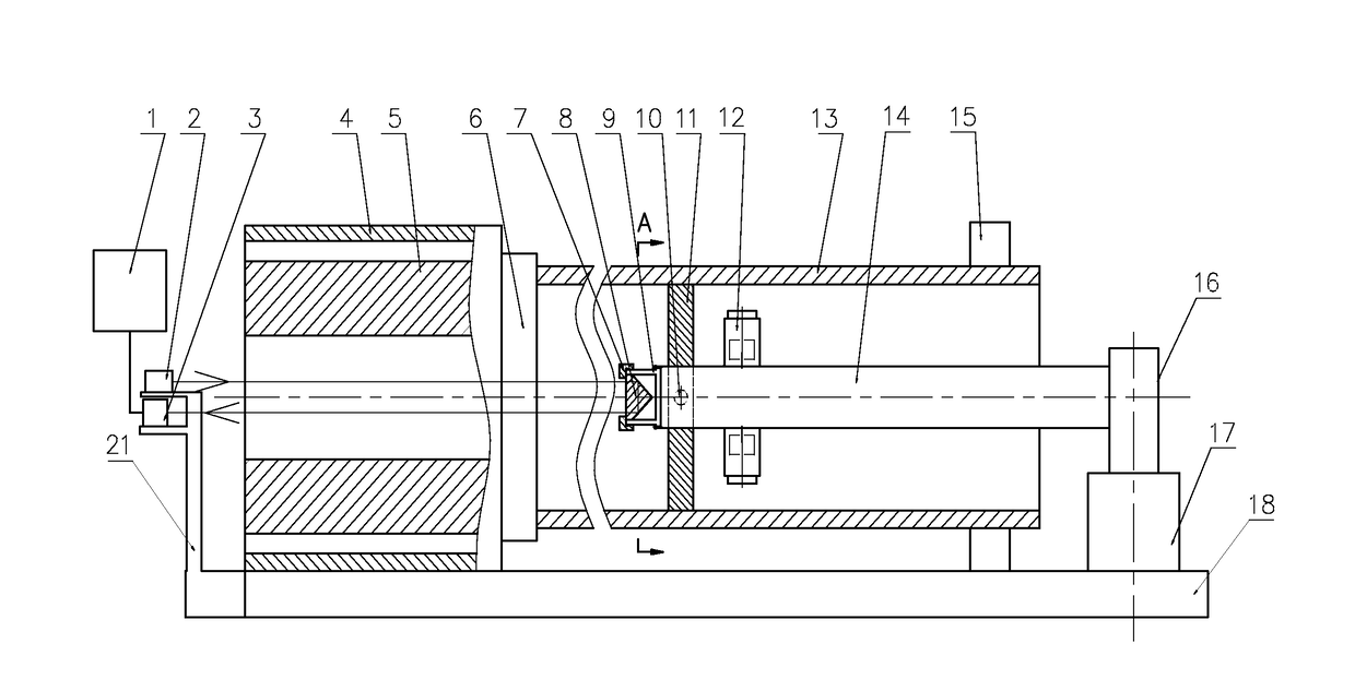
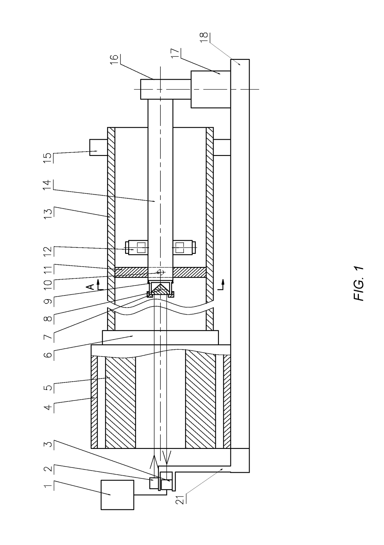
[0022]As shown in FIGS. 1-3, a workpiece 13 rotates and a deep hole cutter 11 feeds. The workpiece 13 is provided with a bottom hole, and a deep hole with a horizontal axis is to be machined.

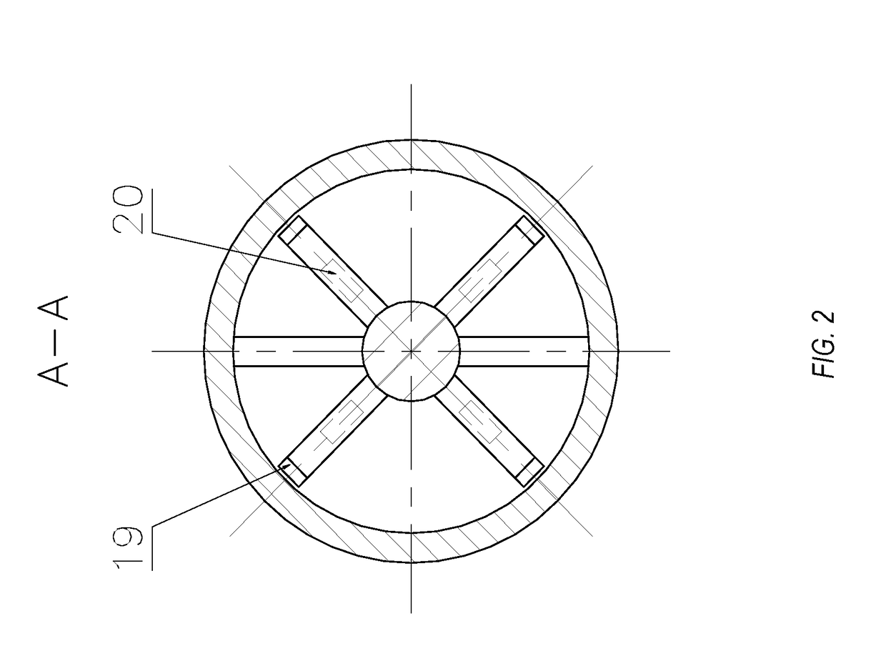
[0023]The present disclosure includes a deep hole cutter 11, a cutter bar 14, a computer 1, a laser transmitter 2, a photosensitive sensor 3, a spindle box 4, a spindle 5, a clamper 6, a pyramid prism support cover 7, a pyramid prism 8, a pyramid prism support 9, a fastening screw 10, iron blocks 12, a center support 15, a cutter bar support 16, a slide plate 17, a machine tool bed 18, wear-resistant blocks 19, heating devices 20, an outer frame 21, a laser orientating block 22 and the like. One end of the workpiece 13 is clamped and positioned by the clamper 6, the ot...


PUM

PropertyMeasurementUnit
diameteraaaaaaaaaa
heightaaaaaaaaaa
surface roughnessaaaaaaaaaa

Abstract

The present disclosure relates to the technical field of deep hole machining, particularly to a rear-mounted deep hole machining on-line detection and deviating correction device, which provide solution to the difficulty in observing the machining site and correcting the cutter deviation in deep hole machining. The device comprises a cutter bar provided with a plurality of iron blocks mounted uniformly in a circumferential direction, wherein each of the iron blocks is provided with a heating device in the interior thereof and a wear-resistant block mounted on the top thereof, wherein mounted on an end face of the other end of the cutter bar is a pyramid prism, wherein a laser transmitter and a photosensitive sensor are mounted in a height corresponding to the height range of the pyramid prism, wherein the incident beam emitted by the laser transmitter is oriented by a laser orientating block. The advantages of the disclosure lie in that the information of the position the deep hole cutter during deep hole machining process and whether the deep hole is skewed or not can be obtained in time, thereby facilitating a solution to the difficulty in detecting the workpiece deep hole straightness and on-line deviating correction, improving the position accuracy such as straightness of the deep hole and reducing the rejection rate of the workpiece.

Description

RELATED APPLICATIONS[0001]The present application claims priority to China Patent Application Serial No. CN 201510774055.2 filed on Nov. 13, 2015, which is hereby incorporated by reference in its entirety.TECHNICAL FIELD[0002]The present disclosure relates to the technical field of deep hole machining, particularly to a rear-mounted deep hole machining on-line detection and deviating correction device.BACKGROUND[0003]Boring, reaming, enlarging or honing a hole means enlarging the diameter of an existing hole such that the accuracy can be improved and the surface roughness can be reduced, and under some circumstances the initially skewing of an axis of the hole can be well corrected.[0004]During the process of deep hole machining, a cutter bar is limited by the hole diameter such that the cutter bar has a small diameter and a long length, resulting in weak rigidity and low strength. During the process of deep hole machining, vibration, corrugation, taper and tilt may often occur, whi...

Claims


Application Information

Patent Timeline
Patent Type & Authority Applications(United States)
IPC IPC(8): B23B41/02B23Q15/14G01S17/42B23B29/02
CPCB23B41/02B23B29/027B23B2260/128G01S17/42B23B2260/092B23Q15/14B23Q17/22B23Q17/2428B24B33/02B23B2270/34B23B2270/48G01S7/497G01S17/06G01S17/88
Inventor SHEN, XINGQUANYU, DAGUOLI, YANLANHUANG, XIAOBINWANG, CHUANGMINBO, XIAOMINGQUAN, BAOLUODONG, ZHEN
Owner ZHONGBEI UNIV
Why Eureka
Try Eureka