
Engine

a technology for engines and engines, applied in the field of engines, can solve problems such as inability to make engine configurations compact, and achieve the effect of compact configuration

Active Publication Date: 2018-08-14
YANMAR POWER TECHNOLOGY CO LTD
View PDF24 Cites 0 Cited by
  • Summary
  • Abstract
  • Description
  • Claims
  • Application Information

AI Technical Summary

Benefits of technology

[0010]In accordance with an engine according to the present invention, a compact configuration can be achieved.

Problems solved by technology

However, in the engine in which the high-pressure turbocharger and the low-pressure turbocharger are disposed close to each other and the high-pressure turbocharger and the low-pressure turbocharger are connected by the intake pipe and the exhaust pipe, space is not utilized in a part (a side) where the high-pressure turbocharger and the low-pressure turbocharger are disposed, which can not make a configuration of the engine compact.

Method used


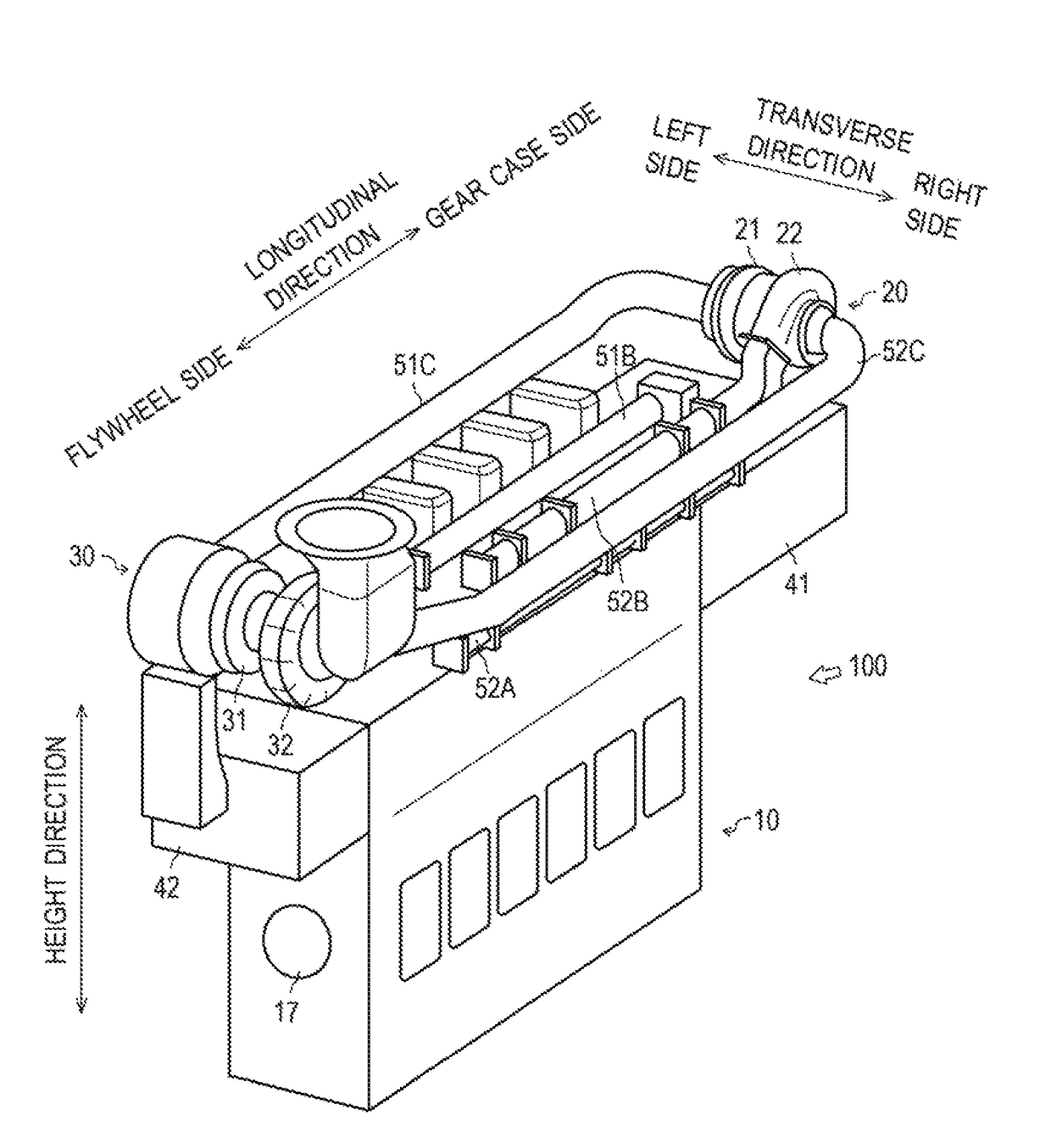
Image

  • Engine
  • Engine
  • Engine

Examples


Embodiment Construction

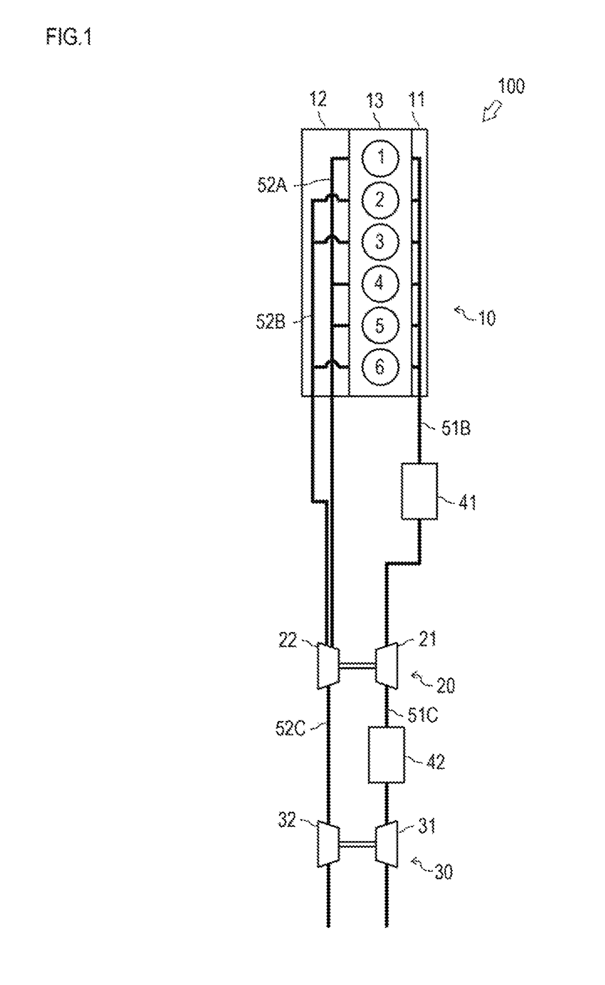
[0017]A configuration of an engine 100 is explained using FIG. 1.

[0018]FIG. 1 schematically shows the configuration of the engine 100.

[0019]The engine 100 is an inline-six diesel engine with a Miller cycle, which has a two-stage turbocharger. The engine 100 includes an engine body 10 and the two-stage turbocharger. The engine 100 of the present embodiment is a marine engine and especially an engine for driving a propeller (a main engine). However, the present invention is not limited to the engine for driving the propeller.

[0020]The engine body 10 includes an intake manifold 11, an exhaust manifold 12, a cylinder block 13, and a cylinder head. The exhaust manifold 12 is of a dynamic pressure type. In the exhaust manifold 12, cylinders 1, 4 and 5 are collected and connected to an exhaust pipe 52A, and cylinders 2, 3 and 6 are collected and connected to an exhaust pipe 52B.

[0021]In the engine 100 of the present embodiment, the exhaust manifold 12 is of the dynamic pressure type such t...


PUM


Abstract

The object of the present invention is to provide a compact engine. An engine has a two-stage turbocharger provided with a high-pressure turbocharger and a low-pressure turbocharger. The high-pressure turbocharger and the low-pressure turbocharger are separately disposed on the gear case side and the flywheel side in along direction of a main body respectively. An intake pipe and an exhaust pipe connecting the high-pressure turbocharger with the low-pressure turbocharger are separately and respectively disposed on right side and left side in a transverse direction of the main body.

Description

TECHNICAL FIELD[0001]The present invention relates to an engine having a two-stage turbocharger provided with a high-pressure turbocharger and a low-pressure turbocharger.BACKGROUND ART[0002]Conventionally, there is known an engine having a two-stage turbocharger. In the engine having the two-stage turbocharger, it is common that the high-pressure turbocharger and the low-pressure turbocharger are disposed close to each other and the high-pressure turbocharger and the low-pressure turbocharger are connected by an intake pipe and an exhaust pipe. For example, JP 06-066146 A discloses an engine in which a high-pressure turbocharger and a low-pressure turbocharger are disposed on one side above a cylinder block.[0003]However, in the engine in which the high-pressure turbocharger and the low-pressure turbocharger are disposed close to each other and the high-pressure turbocharger and the low-pressure turbocharger are connected by the intake pipe and the exhaust pipe, space is not utiliz...

Claims


Application Information

Patent Timeline
Patent Type & Authority Patents(United States)
IPC IPC(8): F02B37/013F01N13/10F02B37/00F02M26/22F02B37/02F02B29/04F02D13/02
CPCF02B37/004F01N13/107F02B29/0412F02B37/013F02B37/025F02D13/0269F02M26/22F02D13/0226Y02T10/146Y02T10/142Y02T10/144Y02T10/12
Inventor NISHIURA, FUMIHIRONODA, TAKEHIROHAMAOKA, SHUNJIKOTOU, FUMIYAHANADA, YUUYA
Owner YANMAR POWER TECHNOLOGY CO LTD
Learn More