Resistance heat assisted cooling and heating technology

a technology of heat assisted cooling and heating technology, applied in the direction of machine operation, light and heating apparatus, transportation and packaging, etc., can solve the problems of reducing the service life of the heated mat. , to achieve the effect of avoiding the cost of a separate system, facilitating the assembly of the seat, and facilitating the heating

Pending Publication Date: 2022-06-02
GENTHERM INC
View PDF0 Cites 2 Cited by
  • Summary
  • Abstract
  • Description
  • Claims
  • Application Information

AI Technical Summary

Benefits of technology

[0019]In that regard, a first aspect of the present invention includes certain features including a heat rod or heat cartridge inserted into or in direct thermal communication with the heat sink or the heat transfer block instead of a prior art separate resistance heated mat.
[0020]Another aspect of the invention includes the use of a resistive heated articulated graphene sheet or other highly flexible conductive material to be used to transfer rapid heating using itself as a resistive heater or being augmented with the separate resistive heating unit. Using the same graphene to transfer heat for heating and cooling that is used for heat generation saves the seat manufacturer from having to add a heating mat which simplifies the seat assembly structure, and avoids the cost of a separate system.
[0021]The invention is particularly useful for applications of the aforementioned heated automotive seats in low temperature situations, along with any other application. For heat only seating applications, sheeted graphene may be used as a resistive heater and also is a widespread heat transfer member instead of a conventional resistance heating mat. By utilizing this material, the seat occupant can be made more comfortable in the cold environment as it provides heat spread across the seat surface, avoiding hot spots in the seat, which also adds to its comfort.
[0022]Instead of a conventional heating mat system, where the resistive heating element is either wire, printed circuit, or woven or non-woven conductive fibrous materials, the present invention allows for the entire surface to be the resistive element where, because of the high thermal conductivity inherent in the proposed graphene or other highly flexible conductive material, a comparatively small area requires heating because the highly thermally conductive graphene or other highly flexible conductive material can transfer the heat across the entire surface of the seat.
[0023]In an attempt to solve the problem presented by the prior art, one aspect of the present invention embeds a small, low cost heating rod or cartridge into the heat transfer block or heat sink of the thermoelectric engine. In a particular application of automotive seats, utilizing the present invention and by employing this concept, the heating time of the thermoelectric assembly to a desired temperature, is greatly improved. This may be a significant factor in allowing the present system to be employed without the use of an added resistance heating mat spread across the seat providing a competitive advantage, as improved performance and lower costs are achieved.
[0024]Although the auxiliary resistive heating concept of the present invention will be described by way of examples hereinbelow for specific aspects having certain features, it must also be realized that minor modifications that do not require undo experimentation on the part of the practitioner are covered within the scope and breadth of this invention. Additional advantages and other novel features of the present invention will be set forth in the description that follows and in particular will be apparent to those skilled in the art upon examination or may be learned within the practice of the invention. Therefore, the invention is capable of many other different aspects and its details are capable of modifications of various aspects which will be obvious to those of ordinary skill in the art all without departing from the spirit of the present invention. Accordingly, the rest of the description will be regarded as illustrative rather than restrictive.

Problems solved by technology

Prior art heated mats do not heat up quickly enough to provide customer satisfaction.
Clearly, this type of system would not be possible with the heating mat.
This system is then especially important in cold ambient temperatures where the temperature dependence of the thermoelectric semiconductor causes it to lose some of its heat pumping effectiveness where there is less heat in a cold heat sink to pump out.

Method used


Image

  • Resistance heat assisted cooling and heating technology
  • Resistance heat assisted cooling and heating technology
  • Resistance heat assisted cooling and heating technology

Examples


Embodiment Construction

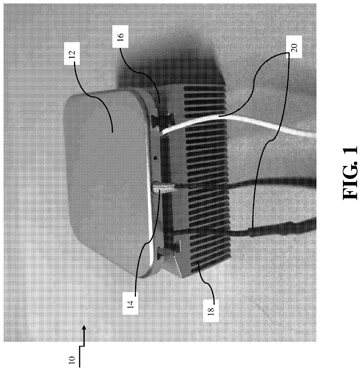
[0039]Referring now to the drawings in detail, FIG. 1 illustrates a portion of a thermoelectric assembly, especially a resistive sheeted thermoelectric assembly, generally denoted by the numeral 10, and including a view of an auxiliary heat rod 14 inserted into and in thermal communication with a heat transfer block 12. Thermoelectric module 16 is sandwiched between heat transfer block 12 and heat sink 18, and is the source of heating for this thermoelectric assembly 10. Thermoelectric module wires 20 are in electrical communication with thermoelectric module 16. By inserting heater cartridge 14 into heat transfer block 12, rapid heating is achievable, as the heating element of the thermoelectric device can be more quickly dedicated to generating heat to comfort a person, more rapidly than if the thermoelectric device was generating heat to increase its operational capabilities.

[0040]Useful materials for the heat rod or heat cartridge include steel, stainless steel, aluminum, brass ...


PUM


Abstract

Various aspects of a rapid effect heat resistant heat and cool assist device is disclosed for providing quick heat and cool comfort to a person, including at least one heat resistant thermal conductor covering a surface area of a heat and cool device for thermal communication to comfort a person, wherein the heat resistant thermal conductor is preferably made of graphene, and has a time to-sensation time period of from 5 seconds to 10 min. and is capable of reaching temperatures from 5° C. to 60° C. for providing heat and cool comfort to a person.

Description

CROSS-REFERENCE TO RELATED APPLICATIONS[0001]This application claims the benefit under 35 U.S.C. 119(e) of U.S. Provisional Application No.: 62 / 812,614 filed on Mar. 1, 2019.STATEMENT REGARDING FEDERALLY SPONSORED RESEARCH OR DEVELOPMENT[0002]Not ApplicableTHE NAMES OF THE PARTIES TO A JOINT RESEARCH AGREEMENT[0003]Not ApplicableINCORPORATION-BY-REFERENCE OF MATERIAL SUBMITTED ON A COMPACT DISC OR AS A TEXT FILE VIA THE OFFICE ELECTRONIC FILING SYSTEM (EFS WEB)[0004]Not ApplicableSTATEMENT REGARDING PRIOR DISCLOSURES BY THE INVENTOR OR A JOINT INVENTOR[0005]Not ApplicableBACKGROUND OF THE INVENTION1. Field of the Invention[0006]The present invention relates to thermoelectric heating systems, methods of manufacturing same, and methods of using same. More particularly, the invention relates to resistance heat assisted cooling and heating technologies.2. Description of the Prior Art[0007]Conventional thermoelectric heating systems are well known in the art, including one of the most co...

Claims


Application Information

Patent Timeline
Patent Type & Authority Applications(United States)
IPC IPC(8): B60N2/56F25B21/04
CPCB60N2/5685F25B2321/023F25B21/04B60N2/5692F25B2321/025
Inventor CAUCHY, CHARLES J.
Owner GENTHERM INC
Why Eureka
Try Eureka