Sheet stacker comprising a sheet flipping device and a holding device

Pending Publication Date: 2022-06-02
CANON PRODN PRINTING HLDG BV
View PDF0 Cites 0 Cited by
  • Summary
  • Abstract
  • Description
  • Claims
  • Application Information

AI Technical Summary

Benefits of technology

[0003]It is an object of the invention to provide more reliable sheet stacking, specific

Problems solved by technology

It is further known that when flipping more rigid sheets, a transport belt may be positioned adjacent the flipping device to force the rigid sheets into the desired flipping motion, for example from US2011309566 AA, U.S. Pat. No. 5,261,655 A, U.S. Pat. No. 5,026,036 A, or U.S. Pat. No. 5,145,167 A. It was f

Method used


Image

  • Sheet stacker comprising a sheet flipping device and a holding device
  • Sheet stacker comprising a sheet flipping device and a holding device
  • Sheet stacker comprising a sheet flipping device and a holding device

Examples


Example

[0039]The present invention will now be described with reference to the accompanying drawings, wherein the same reference numerals have been used to identify the same or similar elements throughout the several views.

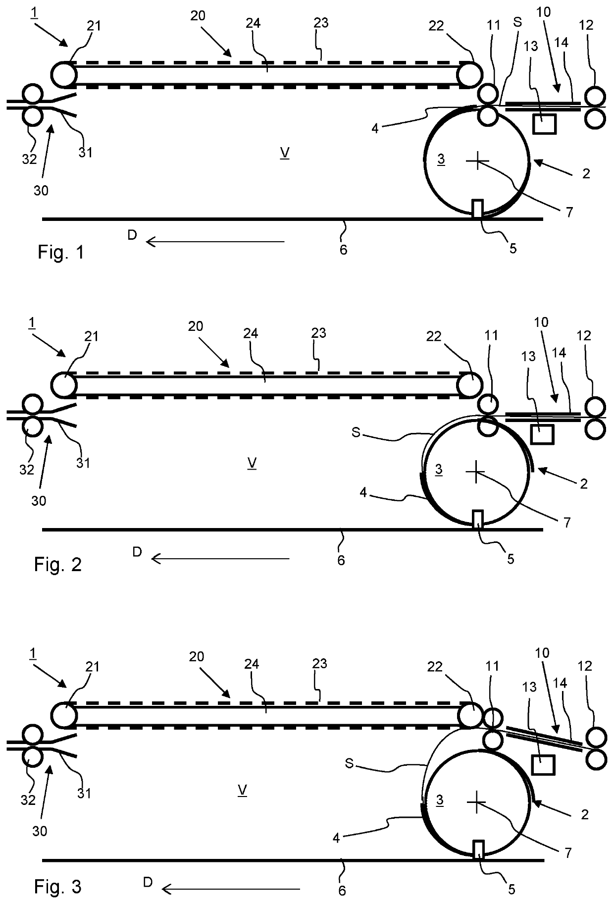
[0040]FIG. 1 illustrates an embodiment of the sheet stacker 1 according to the present invention in the first state wherein the flipping wheel 3 of the flipping device 2 receives a sheet S from the sheet supply path 10 into one of its receiving slots 4. The flipping device 2 is configured to rotate around its flipping axis 7, such that a sheet S held in the slot 4 is flipped through partially flipped through the flipping volume V. The leading edge of the sheet S is stopped at the stop element 5, which ejects the sheet S from the slot 4. The stop element 5 is provided at a position along the circumference of the flipping wheel 3. The flipping motion will be completed by further feeding the trailing portion of the sheet S into the flipping volume V. The flipped sheet S is ...


PUM

PropertyMeasurementUnit
Volumeaaaaaaaaaa
Gravityaaaaaaaaaa
Distanceaaaaaaaaaa

Abstract

During flipping sheets may fold upon themselves under the influence of gravity. To prevent a sheet stacker is provided with a holding device for releasably holding at least a portion of the sheet at least partially during the flipping of the sheet by a sheet flipping device, wherein the holding device is configured for movement of the held portion of the sheet in a first direction perpendicular to the flipping axis.

Description

BACKGROUND OF THE INVENTION1. Field of the invention[0001]The invention relates to a sheet stacker, a printer comprising such a sheet stacker, and a method for stacking sheets.2. Description of Background Art[0002]Sheet stackers, specifically those used for medium-to-large volume printers, may comprise a sheet flipping device, which reverses the orientation of the sheet during the stacking process. Such sheets stackers are known e.g. from EP 2776352 A1. It is further known that when flipping more rigid sheets, a transport belt may be positioned adjacent the flipping device to force the rigid sheets into the desired flipping motion, for example from US2011309566 AA, U.S. Pat. No. 5,261,655 A, U.S. Pat. No. 5,026,036 A, or U.S. Pat. No. 5,145,167 A. It was found that such configurations were not able to more reliably and stack relatively very flexible sheets, such as (long) paper sheets with low grammage or thin foils. It was found that sheets could collapse upon themselves during fli...

Claims


Application Information

Patent Timeline
IPC IPC(8): B65H29/22B65H29/24B65H29/40
CPCB65H29/22B65H29/242B65H29/40B65H2406/323B65H2404/651B65H2301/4212B65H2404/6551B65H29/60B65H2801/31B65H2404/63
Inventor VERHOEVEN, ERIK P.J.PEULEN, JOHANNES E.P.
Owner CANON PRODN PRINTING HLDG BV
Why Eureka
Try Eureka